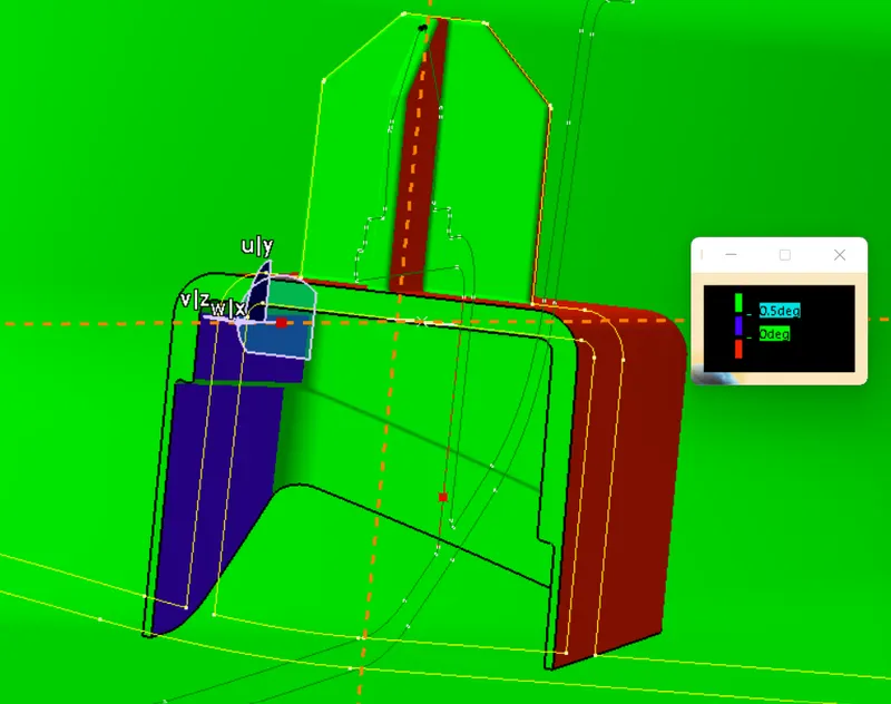
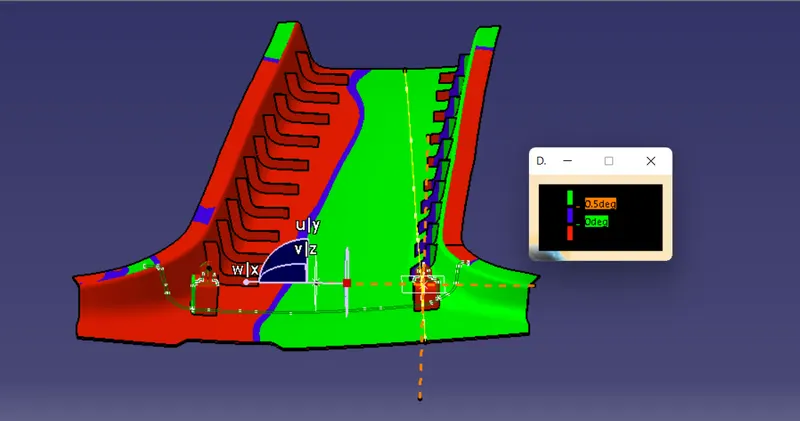
Week 9 - Project - Master Section Development
Master Section Development for B-Pillar in an automobile:
Objectives:
a) Create B, C surfaces from given A-surface of B-pillar following OEM rules.
b) Create engineering features (dog house, 4-way locator, ribs) using mastersections given.
c) Perform draft analysis on A-surface, Solid B-pillar, engineering features using main and side core tooling axis.
Tooling axis:
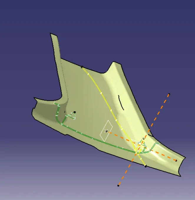
First the draft analysis is done for the A-surface of B-pillar. For that a tooling axis needs to be created. This is done with help of the master sections given by bisecting method. The master section represents dog house along with a 4-way locator.
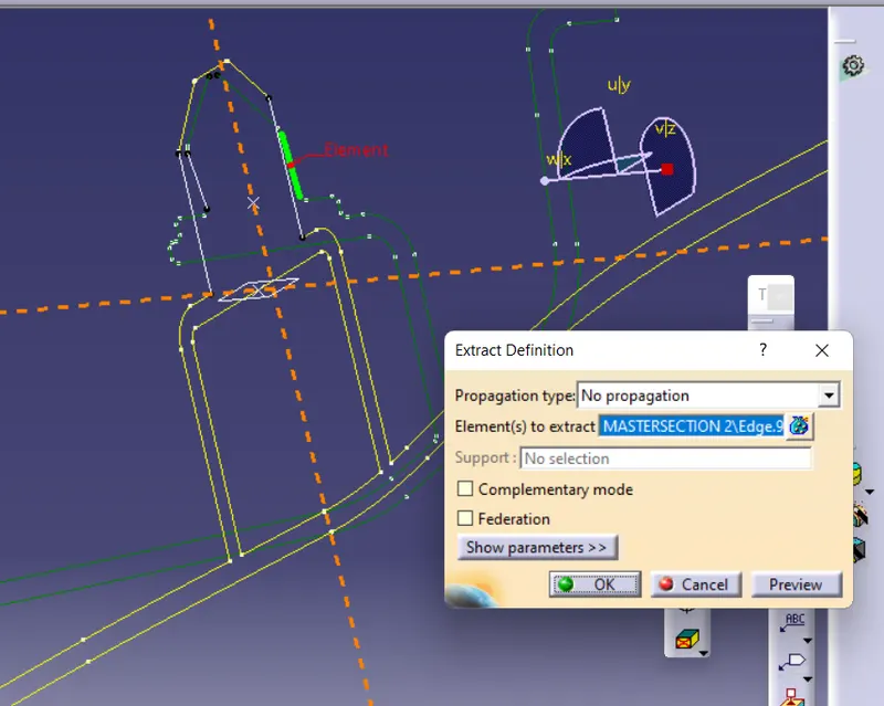
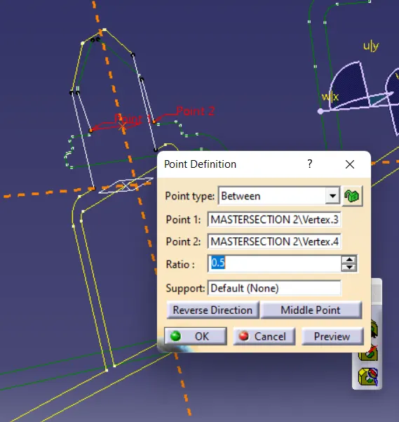
The following lines are extracted from the two master sections as shown. Then place a point in mid of the extracted lines. Two lines are created with point as reference using bisecting method. The main tooling axis is drawn by bisecting these two lines.

Draft analysis of class-A surface:
Make sure that the class-A surface is uniform. If there are any errors in patches solve them using multisection surface, fill surface commands.
The draft analysis is done with following steps:
a) Select Materials option in view mode customization toolbar.
b) Select 'Feature draft analysis in "Analysis" option.
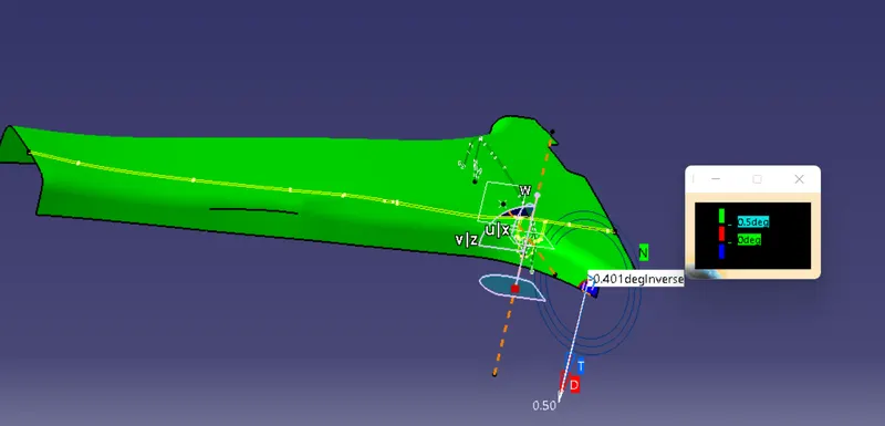
c) In the draft analysis dialog box, select compass button, orient the compass in tooling axis direction
d) Lock the orientation and select anywhere on the surface to get the complete analysis of the surface.
Identify areas in surface of positve draft if there are any negative angles.
Class-B surface creation:
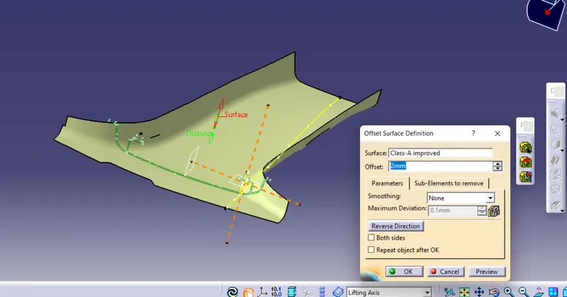
In general the planar surfaces of class-A are extracted and offsetted. In this case, the entire class-A is offsetted for 2mm. There may be some patches missing in the offset. These are resolved using multisurface section command. Throught the mastersection we observe that there should be some horizontal flanges created.
Flanges:
Extract the edges of A-surface as shown below.
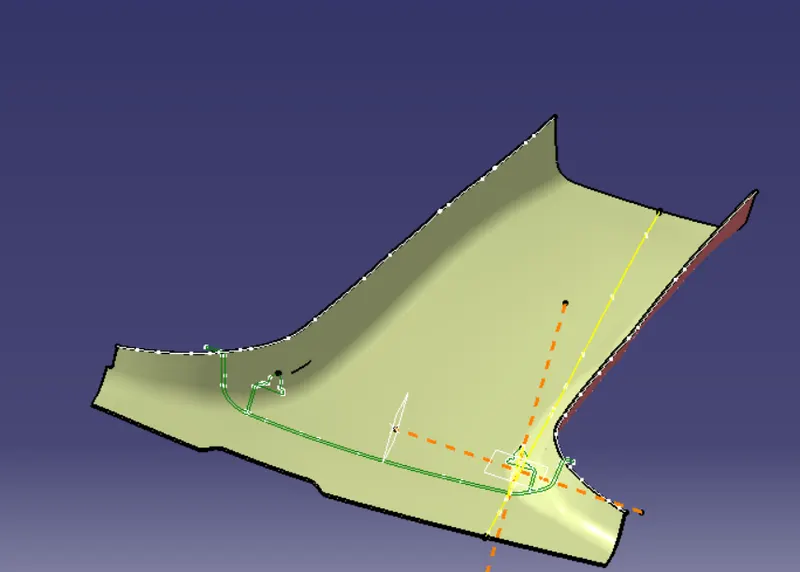
The curves are smoothened. Extract the the surfaces on which the curves lie. Using 'with reference surface' option in sweep command, create a flange by giving proper angle checking with mastersection. These two flanges are offsetted to 2mm. Now, A,B surfaces and flanges are trimmed with each to get the required shape.
C-surface:
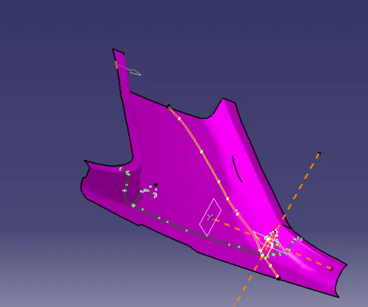
The outer edges of A-surface are extracted seperately as shown. For flat curves C-surface is generated giving 3-degree angle. The edges with curvatur are covered using multi-section surface command. All the swept and multi-section surfaces are joined to form the C-surface.
The C-surface is trimmed with A-surface. This unit is then trimmed with B-surface to form a closed surface.
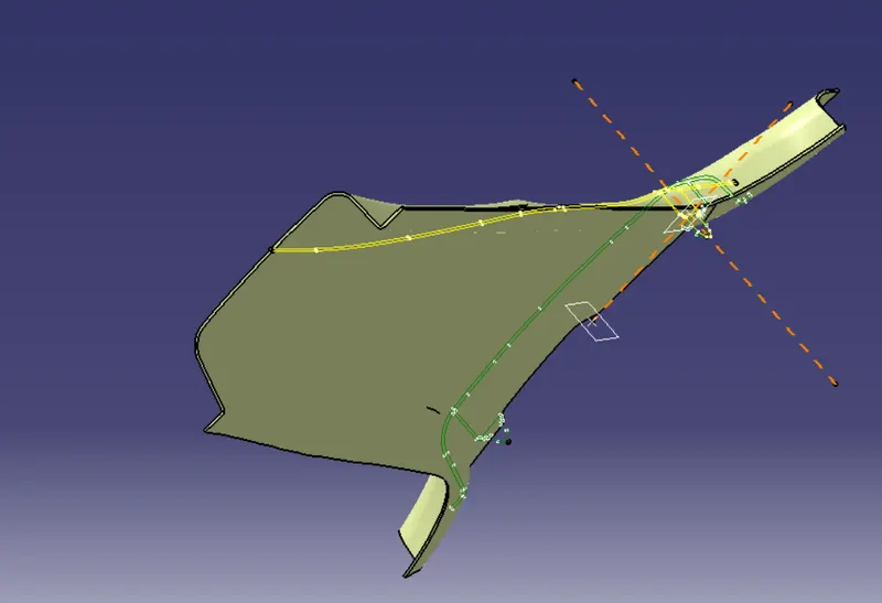
Using closed surface command the surface is converted to a solid object.
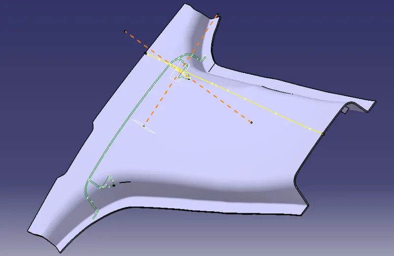
Engineering features:
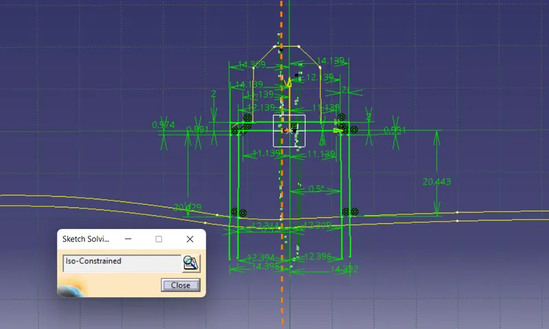
On the closed surface engineering features i.e, doghouse, 4-way locator, ribs should be created. This is done taking the help of master section. Consider the master section shown below. Create a plane on the section.
The dog house is created using following steps:
a) Create a sketch with plane and point as references. Sketch the master section inner part as shown. Extrude and thicken it into a solid object.
b) Extract the outer edges of the other master section and extrude them into surfaces. Split the solid object using these surfaces. Create the lower cut in doghouse by offsetting and properly trimming the B-surface.
c) The solid object is split with the trimmed surface to get the final dog house. Now create a plane perpendicular to previously created plane on dog house.
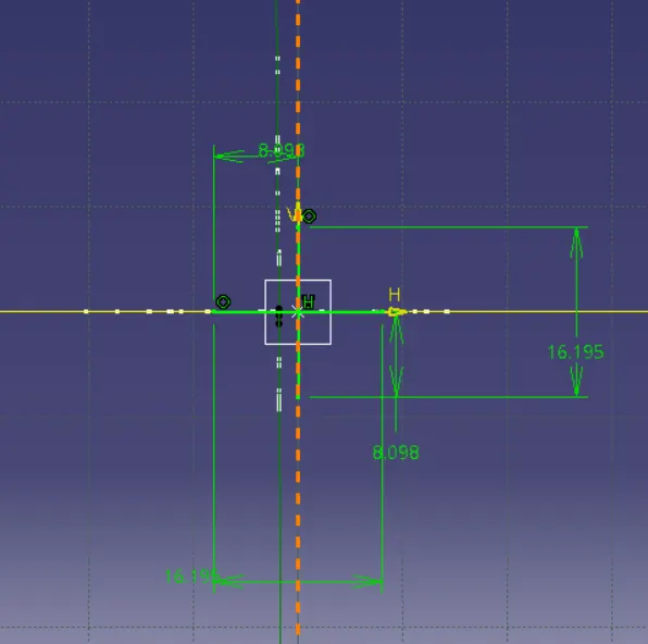
d) Using both master secions create a proper sketch and convert it into a solid object. Assemble this with dog house.
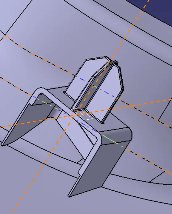
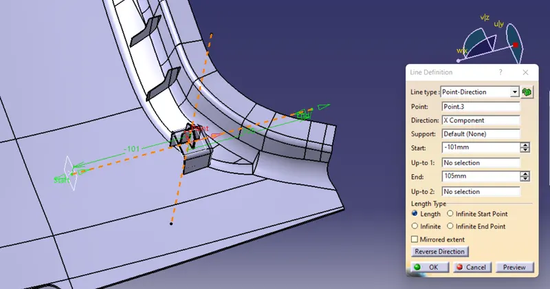
The dog house and locator assembly cannot be cleared using main tooling axis. So a side core tooling axis also called lofter axis is created. This axis is perpendicular to main tooling axis.
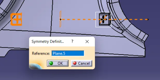
The dog house assembly is duplicated to other side of B-pillar using symmetry command. Verify both the doghouses with mastersections given.
Ribs:
The ribs should be 50mm apart from each starting from the dog house. Using the design rules, the ribs should have,
Thickness: 0.4*2= 0.8mm
Height: 5*2= 10mm
Fillet radius = 0.3mm
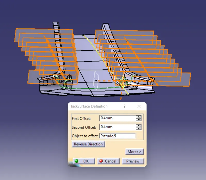
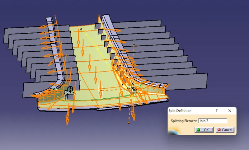
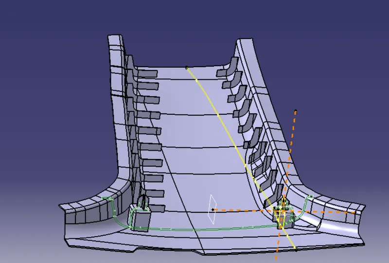
The ribs, doghouse assembly are joined with B-pillar.
Draft analysis:
B-pillar with engineering features:
Same procedure as A-surface is to be followed to perform draft analysis of B-pillar.
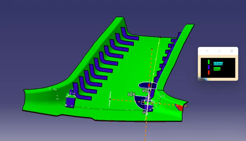
The analysis is performed with respect to Main tooling and Lifter axis.
About Main tooling axis:
About Lifter axis: