Week 9 - Project - Master Section Development
Aim :
- The objective of this project is to develop a Closed Surface Model using Master Sections
- To develop attachment features for Fixation of Parts by following OEM Design standards and procedures in CATIA SURFACE WORKBENCH and PART DESIGN
Description :
Master Section :
Master Sections are the guides for design requirements that shape the component after Class A Surfaces' technical styling.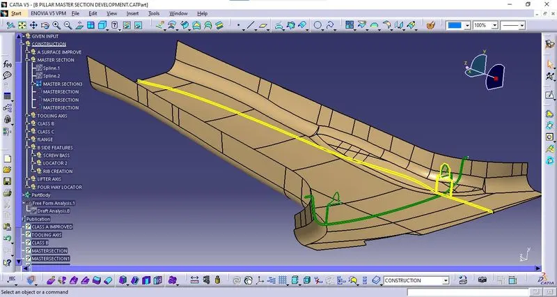
Class A Improvement :
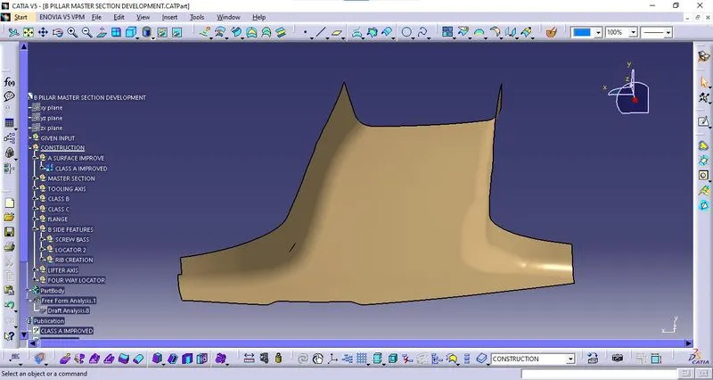
Class A is connected using the join option.
Main Tooling Axis Creation:
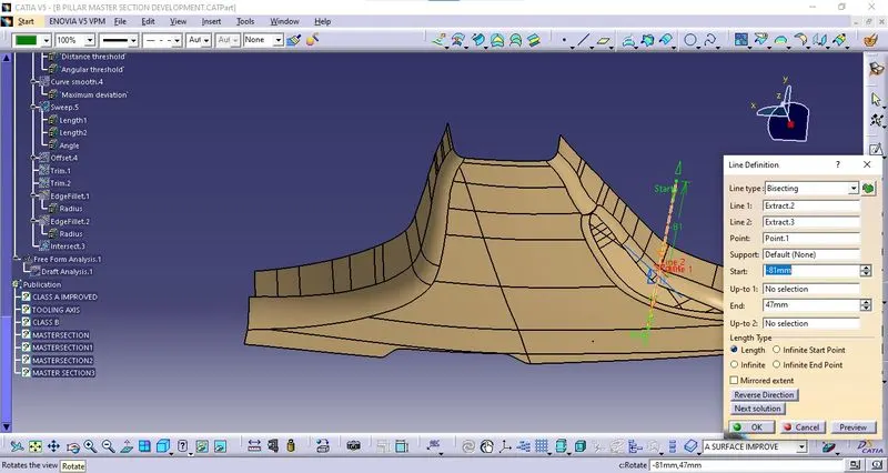
- To Find The Tooling Direction We Use The Master section For The Engineering Feature.
- Here We Take The Two Boundaries And Find a Bisecting Line Between Them
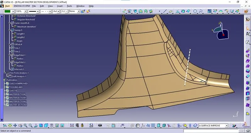
- Finally, the Tooling axis is created by bisecting the two lines and it is published.
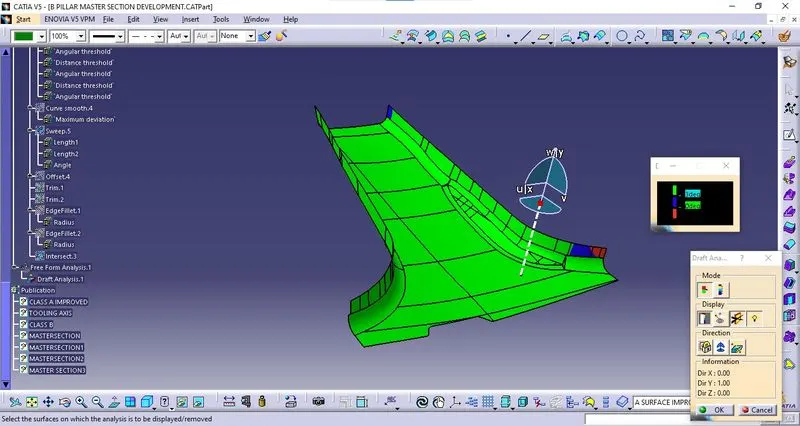
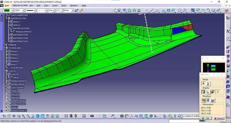
Manufacturing Feasibility Of The A-Surface (Draft Analysis):
- Once the model is prepared and the Tooling axis is created then the Draft analysis is done on the surface.
- To perform Draft Analysis,
- Go to the insert Menu >> Click Analysis >> Click Feature Draft Analysis option >> New Dialog boxes open.
- Select the Elements as the Class-A Model and the Direction as the Tooling Axis using the Compass option to define a new direction of the draft.
- Click OK to check if all the surfaces come under the limits of 0 to 3 degrees.
- If the draft is more than 3 Degree then the surface will be shown as green.
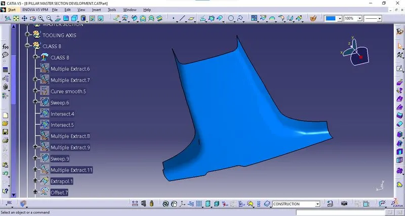
class B :
- Offset the Class-A surface to 2mm for Class B.
- Finally, Class B is created.
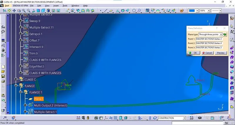
Flanges :
- First, we create the plane on the master section, we take three points for the plane.
- Finally, the plane is created
Flange Creation
- According To The Master Section, The B-Pillar Has Flanges On Both Sides.
- The Flanges Have To Be Included In The Design And The A And B Surface Has To Be Modified.
- The Surfaces Should Match The Master Section.
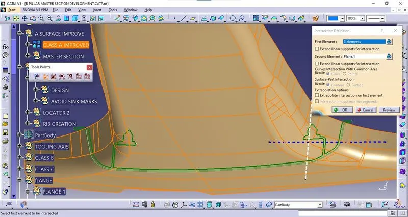
Class A Flanges :
We take a section of Class A and plane 1
Sweep 1:
- We take the extract of class A edges and extract of adjacent surfaces.
- In sweep go-to reference surface then pick the guide curve and reference surface.
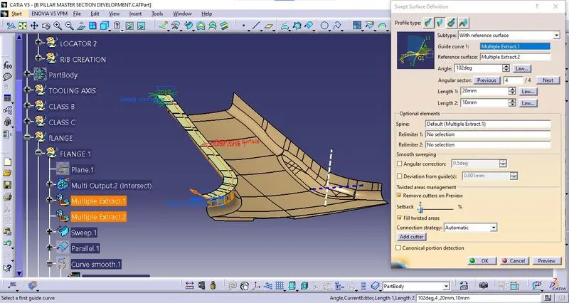
Offset :
offset the sweep to 1.454 mm to meet the master section boundary at 0mm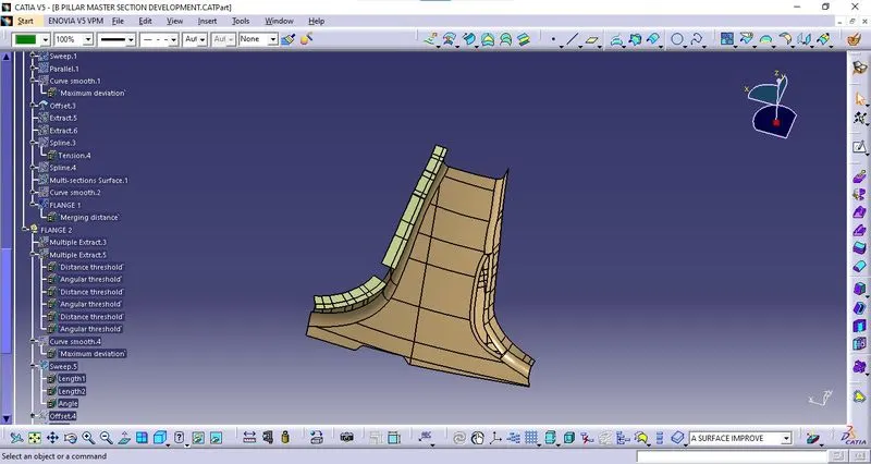 .
.
Multi-Section surface :
Offset surface error covers using multi-section surface.
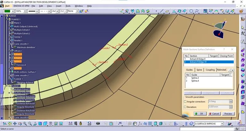
Flange 1 :
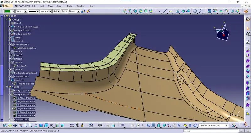
Sweep 2 :
- We take the extract of class A edges and extract of adjacent surfaces.
- In sweep go-to reference surface then pick the guide curve and reference surface.
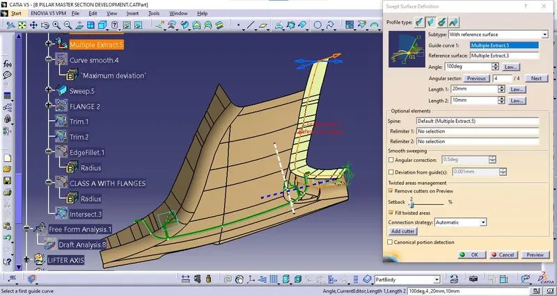
Flange 2 :
offset the sweep to 0.489 mm to meet the master section boundary at 0mm
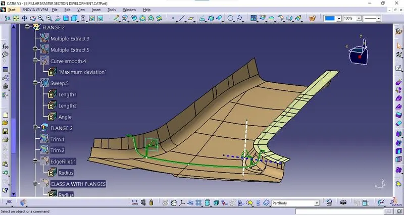
Final Trim of Class A Flanges :
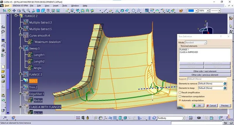
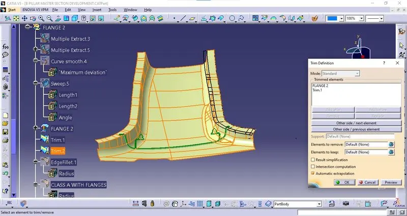
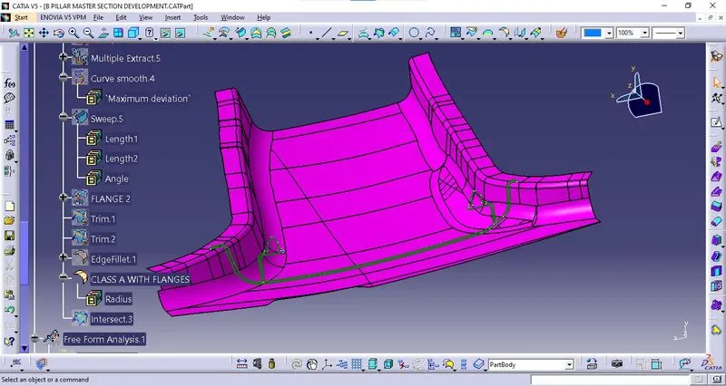
Fillets of Class A :
Give edges fillets of 5mm to flanges edges.
Class B Flanges :
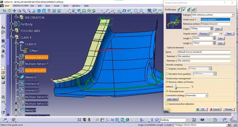
Sweep 3 :
- We take the extract of class A edges and extract of adjacent surfaces.
- In sweep go-to reference surface then pick the guide curve and reference surface.
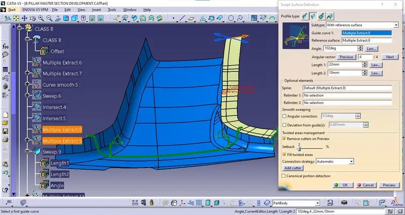
Sweep 4 :
- We take the extract of class A edges and extract of adjacent surfaces.
- In sweep go-to reference surface then pick the guide curve and reference surface.
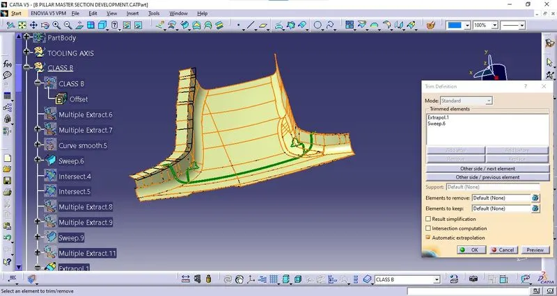
Final Trim of Class B Flanges :
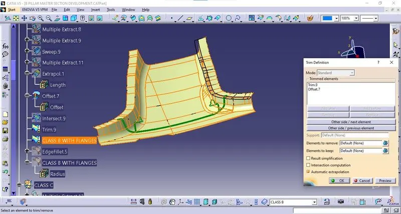
Fillets of Class B Flanges :
Give edges fillets of 4.5 mm to flanges edges.
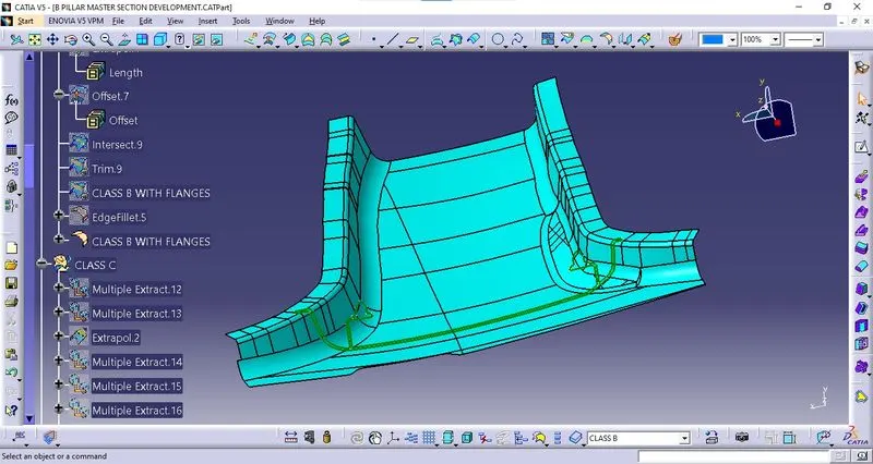
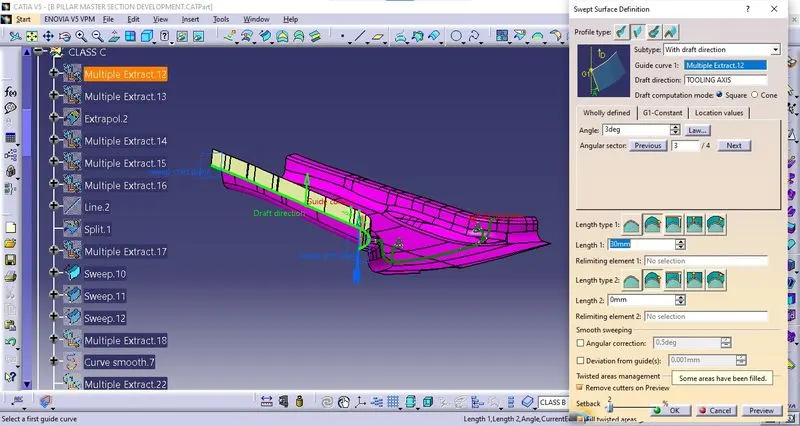
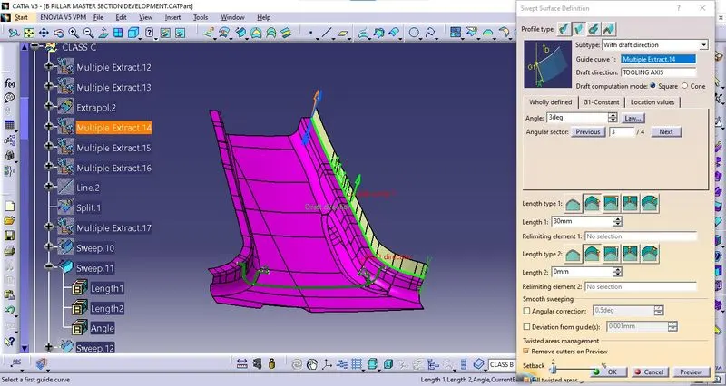
Class C Creation :
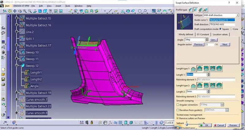
Final trim of Class C :
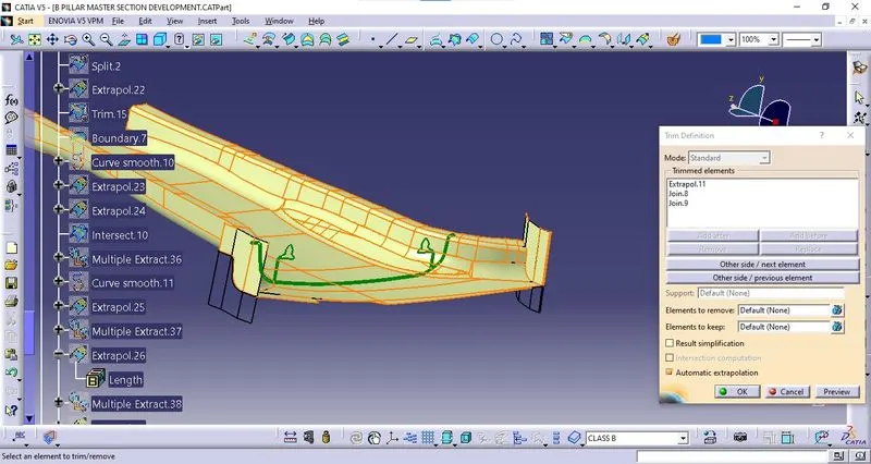
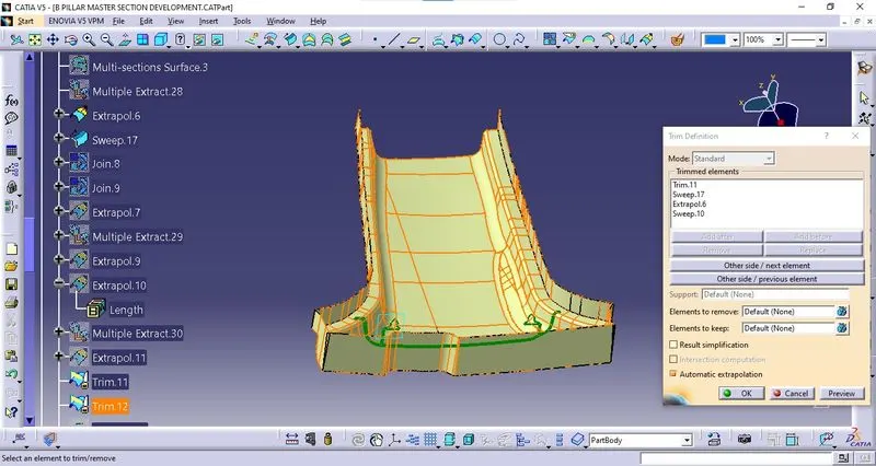
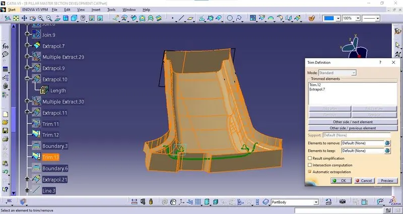
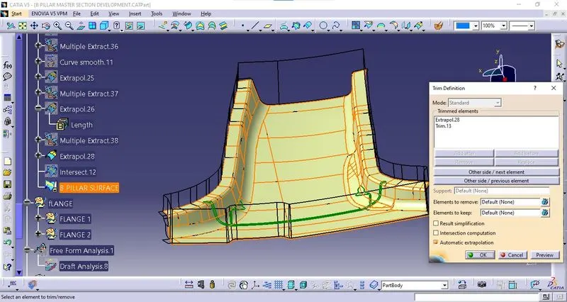
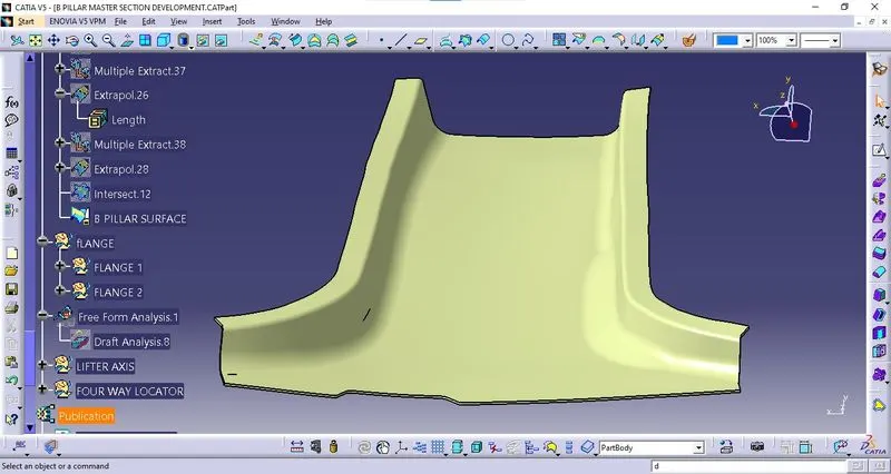
Final Trim of B Pillar Closed surface :
- Now, start with joining the Class A and Class C surfaces together.
- Next, trim the combined surface with the Class B Surface to create the final surface.
Surface convert into the solid body :
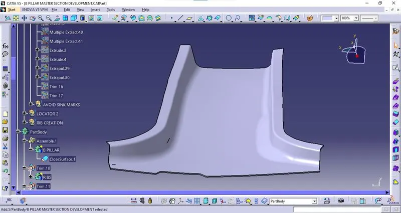
- After creating the surface, go to the Part design option and create the solid using the closed surface option.
- The solid is created.
B Side Feature used in B-pillar Creation :
- Doghouse
- 4-way Locator
- Ribs
Procedure for dog house creation :
- To create a Doghouse, Create the sketch on the Surface face, such that there are 3 sides are created and constraint it.
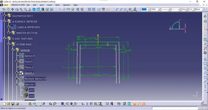
- Exit the Sketcher Workbench.
- After exiting the sketcher workbench, Open the Generative Shape design and extract the sketch.
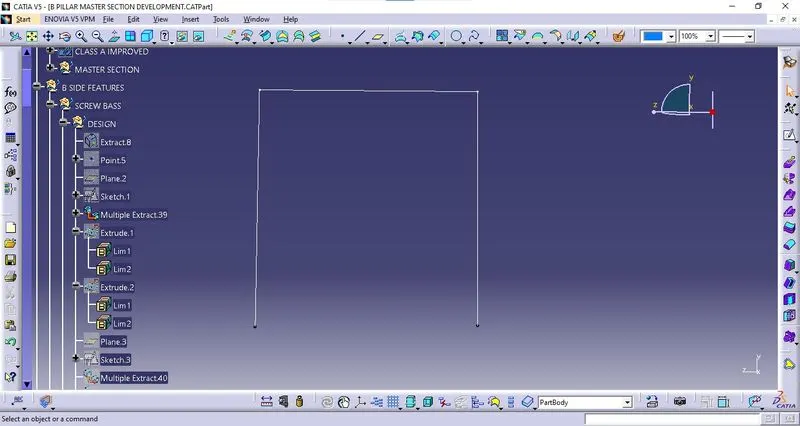
- Extracted sketch to extrude
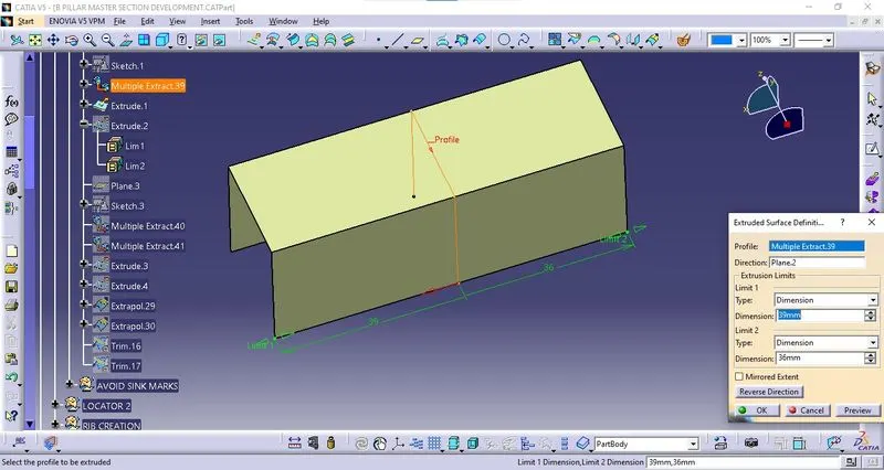
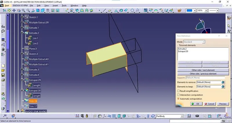
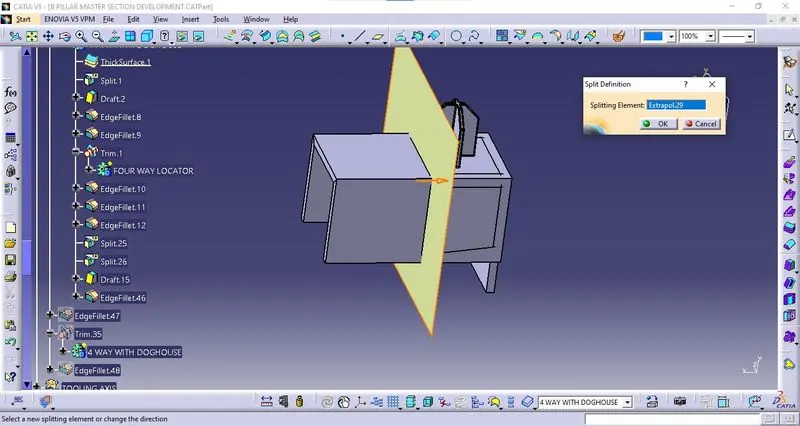
Trim the extrude with extrapolated surface
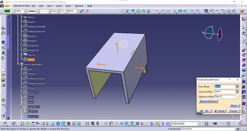
After creating the surface, go to the Part design option and create the solid using the thicken option.
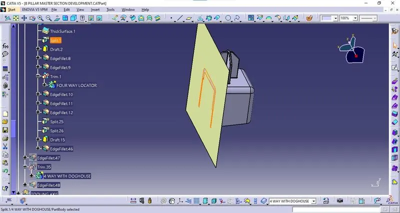
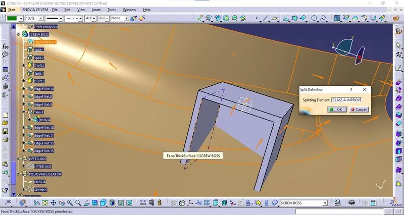
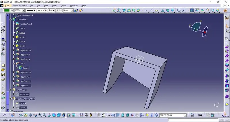
Using the split option cuts the front face and bottom face.
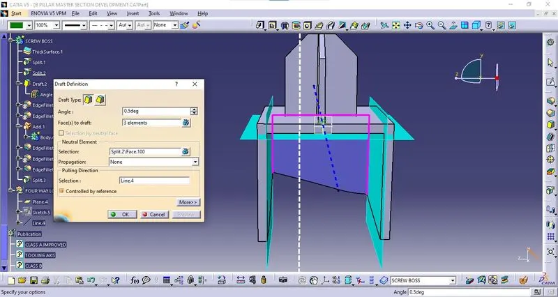
Draft :
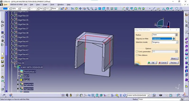
Fillets :
Give the edges fillet of 1mm to the inside doghouse edges.
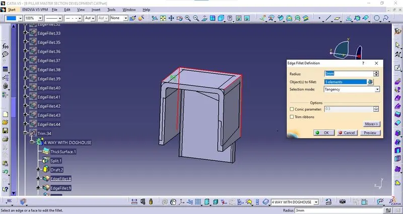
Give the edges fillet of 3 mm to the outside doghouse edges.
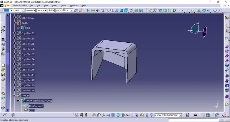
Split the Undercut :
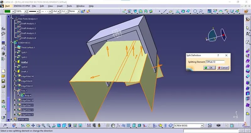
Undercut as shown in the figure.
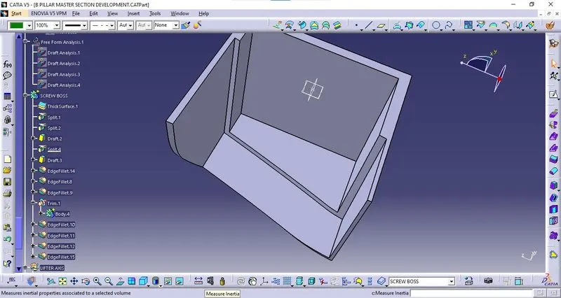
Fillet undercut :
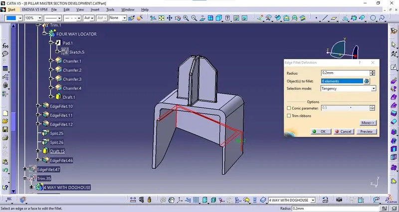
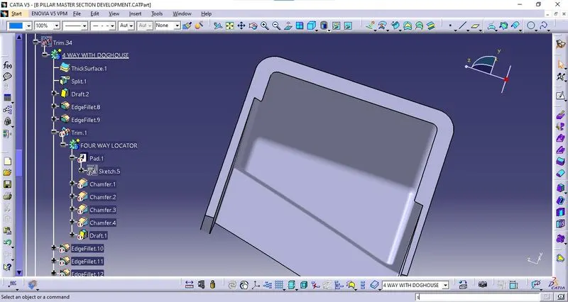
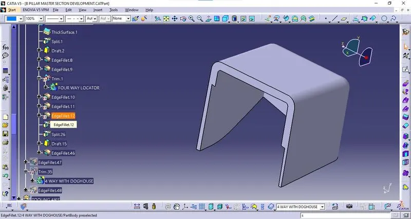
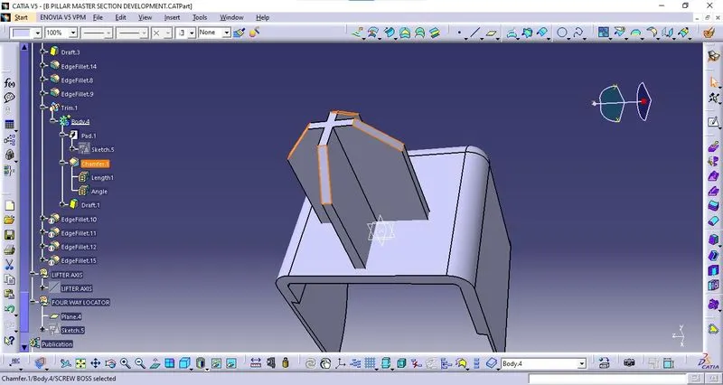
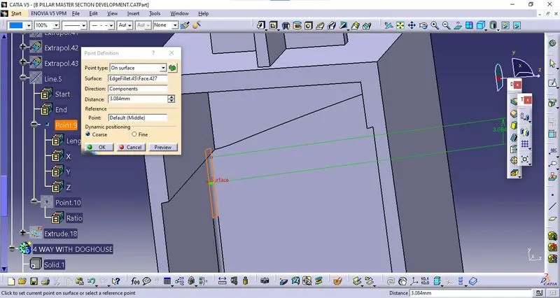
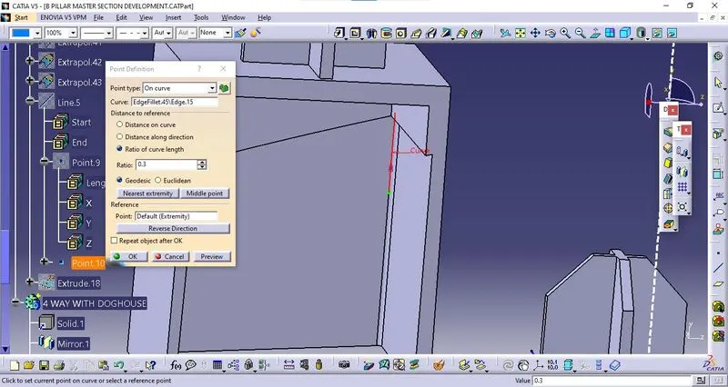
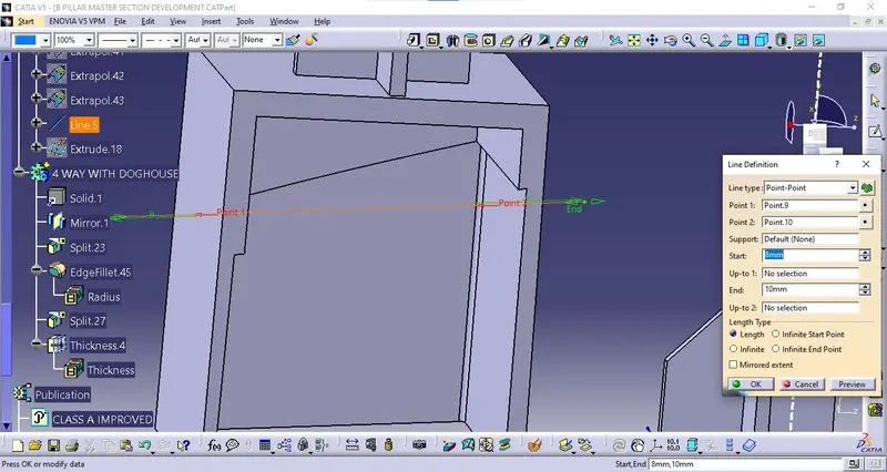
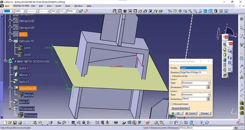
Procedure for 4 Way locator :
Sketch for 4-way locator
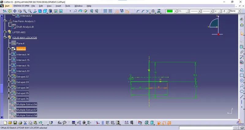
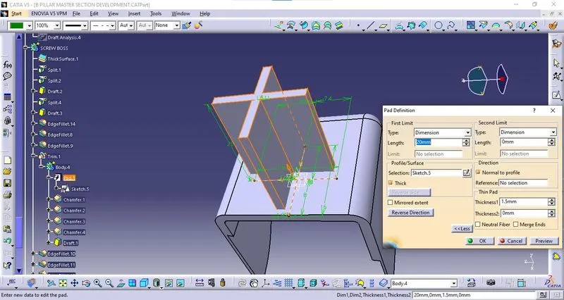
Pad the sketch by switching the workbench to Part Design workbench
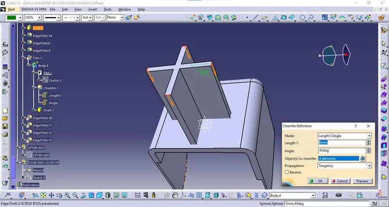
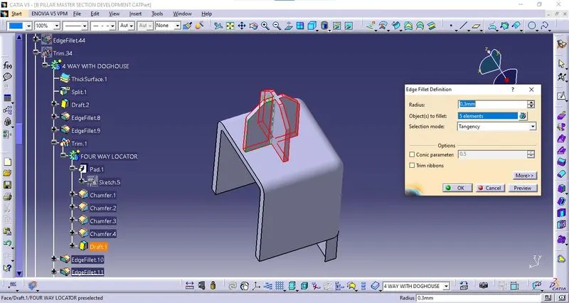
Fillet :
Give the edge fillet of 0.3 mm to the 4 way locator edges.
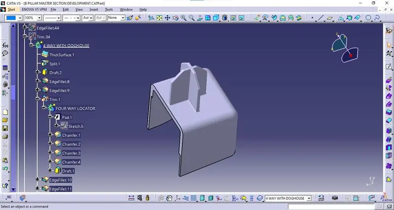
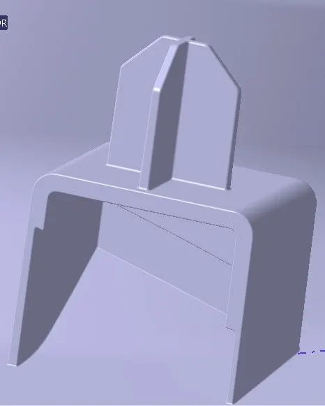
Final Doghouse with 4 Way locator :
Second Doghouse :
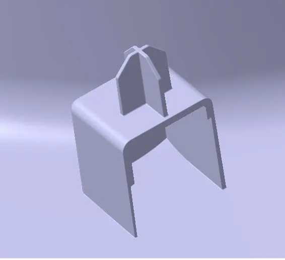
Second doghouse is created by using the mirror option in part design.
Split :
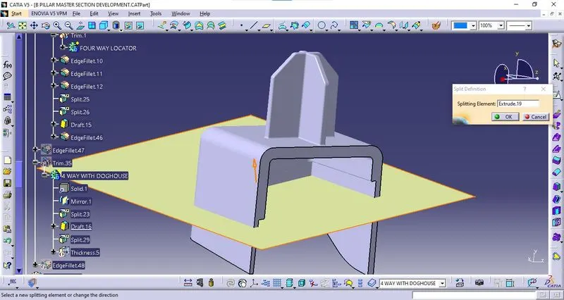
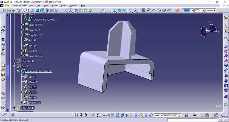
Thickness :
splited face give the thickness of 30mm to the bottom face of the doghouse.
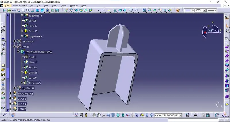
Final second doghouse:
Procedure for Ribs creation :
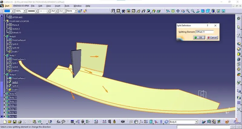
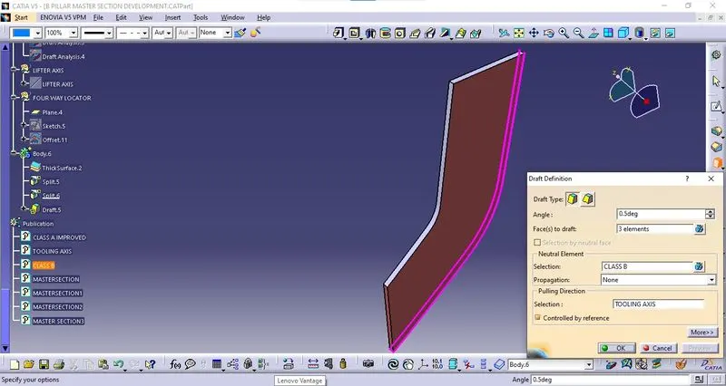
- To create the Ribs, Go to the Sketcher workbench and draw a straight line on the face you want to create a rib and constraint it.
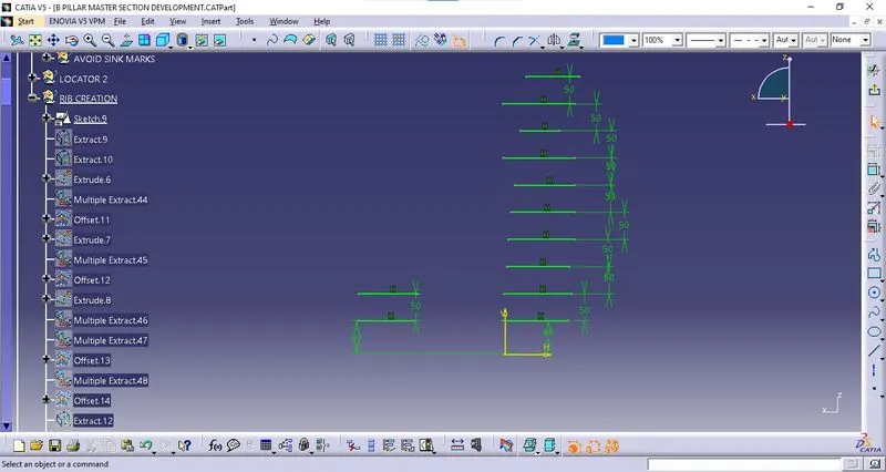
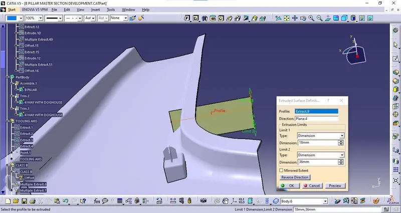
- Exit the Sketcher workbench and Open the Generative shape design
- Extract the sketch then the extracted line to extrude in-plane direction.
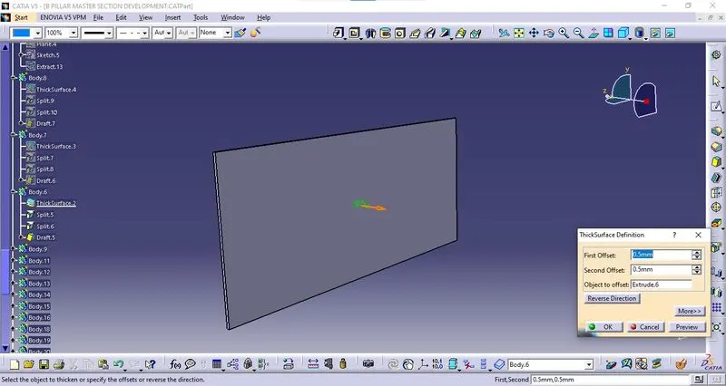
- Using the thicken option to create the solid component
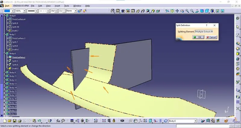
Split :
Draft :
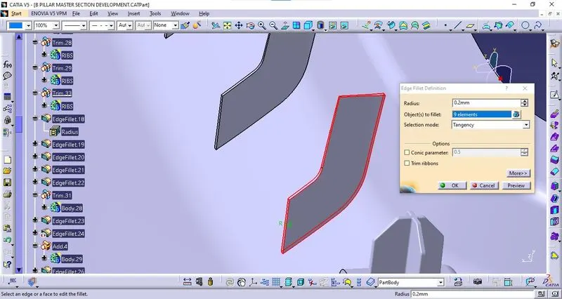
Fillets :
Give the edges fillets of 0.2 mm to rib edges.
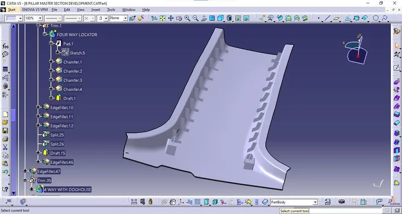
Final Ribs :
- Now copy the Part body and paste it on the main Tree Structure(Note: Paste it with the option “Paste Special >>Paste with the Link).
- Use the Translate option to move the copied rib part body from the starting point to the ending 50mm point.
- Follow the above steps repeatedly to create the ribs on both sides.
- The Final Solid component is created.
Draft Analysis :
- Once the model is prepared and the Tooling axis is created then the Draft analysis is done on the surface.
- To perform Draft Analysis, Go to the insert Menu >> Click Analysis >> Click Feature Draft Analysis option >> New Dialog boxes opens.
- Select the Elements as the Class-B Model and the Direction as the Tooling Axis
- using the Compass option to define a new direction of the draft.
- Click OK to check if all the surfaces come under the limits of 0 to 3 degrees.
- If the draft is more than 3 Degree then the surface will be shown as green.
Doghouse :
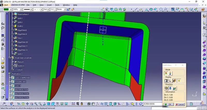
- Once the model is prepared and the Tooling axis is created then the Draft analysis is done on the surface.
- To perform Draft Analysis, Go to the insert Menu >> Click Analysis >> Click Feature Draft Analysis option >> New Dialog boxes opens.
- Select the Elements as the Doghouse Model and the Direction as the tooling axis.
- using the Compass option to define a new direction of the draft.
- Click OK to check if all the surfaces come under the limits of 0 to 3 degrees.
- If the draft is more than 3 Degree then the surface will be shown as green.
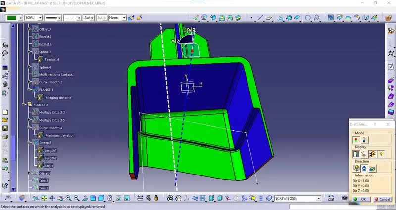
- Select the Elements as the Doghouse Model and the Direction as the tooling axis.
- The minimum draft of 0.48deg to the doghouse.
t