Week 9 - Project - Master Section Development
B Pillar Design using Master Sections and class A Surface
The body of an automobile is made of a structure that is just the same as that of a house. It has similar components, which include the roof, the pillars, and the floor. The car pillar in the vehicle stands in the near-vertical position, which supports the vehicle’s roof. However, the A-pillar and the D pillar stand inclined in some vehicles for aerodynamic reasons.
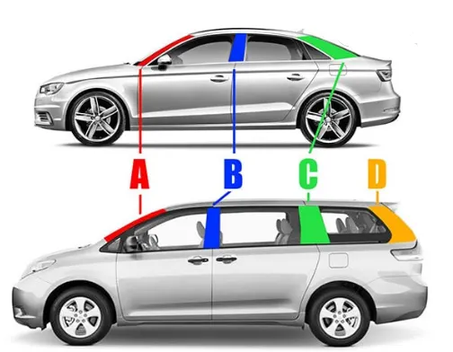
The above picture denotes the diffferent pillars out of which B Pillar is the most complex component/structure of the vehicle body. This is because the front door closes on the B pillar while the rear door hinges onto it. The B pillar or the center pillar in vehicles is made of steel. It is welded to roof panel on top and the vehicle’s floor pan at the bottom. This pillar provides structural support to the vehicle’s roof.
Design Approach
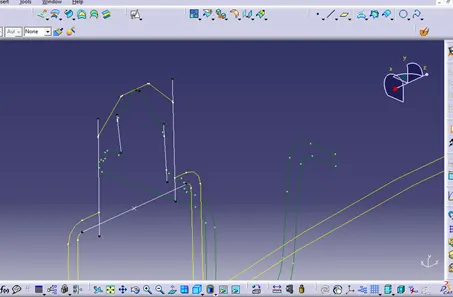
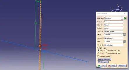
The First step is to create the tooling axis and it is created from the provided tooling axis. For Tooling Axis creation the bottom portion of the locator in the master section are extracted and bisceting lines are created from the either ends and they are further bisected to obtain the Tooling Axis.
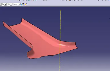
Once the Tooling axis is created draft analysis can be done on the class A surface. Draft tool is selected and using the compass tool the tooling axis is selected and locked then the surface is clicked to obtained the draft.
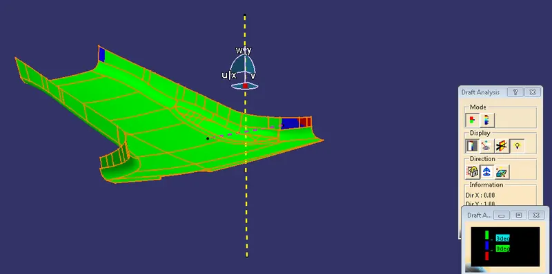
The fig shows that the surface have a 3 deg draft excepft for a few patches with negative and zer draft which can be ignored but under the decretion of the class A team.
Part Body Creation:
The first step is to create flanges for the class a, for that the area near the edges are extracted and boundary is creaed at the edges.
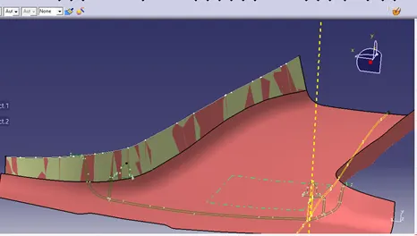
After this the boundary is now swept with certain angle, master sections can be used to obtain the accurate angle of sweep
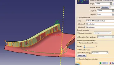
After sweep is created an intersection is created with respect to the master section so that we can correct the sweep with master section. The sweep is corrected by means of offset to match the master section.
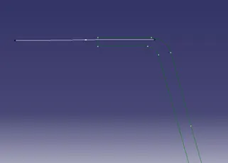
Once the required sweep is obtained they are trimmed with class a to obtain the new improved class a with flanges. Fillet is applied and the new surface is compared with master section for any defects.
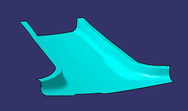
For B surface creation the newly improved surface is offseted to 2mm.
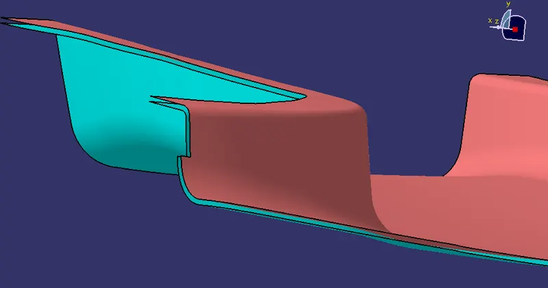
For Class C surface creation the boundary of class a is axtracted and sweeped perpendicular to class a and they are extended beyond class b.
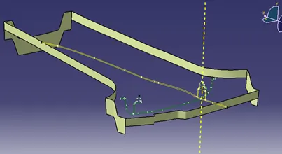
Class C is then trimmed with class a and b surface to obatin the part surface.
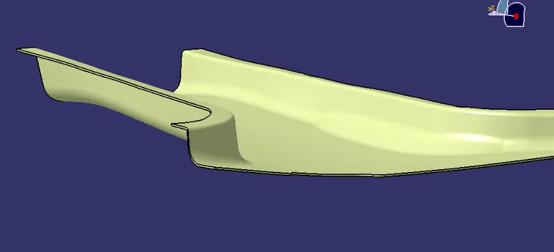
Once surface is created part body is selected and close surface tool is used to creat the part body.
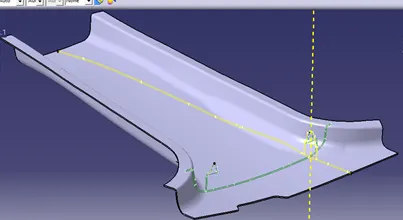
Next step is the creation of B side features ie the doghouse and 4 way locators. First the doghouse is created by creating a sketch in master section. the inner profile is projected and then extruded in both sides.
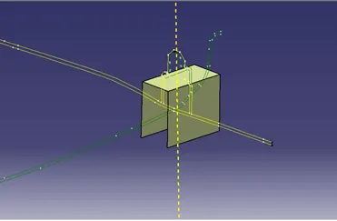
To clear certain areas of the doghouse an additional side core or slider axis is required. A line created in the direction od extrution acts as the slider axis.
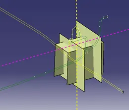
The two extremes of doghouse are extracted and extruded and one end is slpitted to form the closewd end and they are thickened via part body.
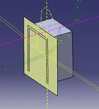
To avoid sink marks on class a bottom of the dog ohuse is made 40% of the part thickness, offset of inner doghouse walls are used and they are split from the part body.
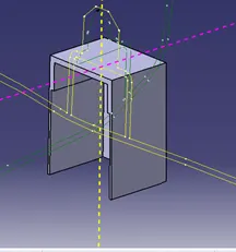
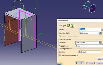
Draft of 0.5 deg is applied on the inner walls
The next step is 4 way locator creation, for this a positioned sketch is created on top of the dog house and they are extruded with thickness
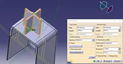
Chamfer and fillet are applied to the edges.
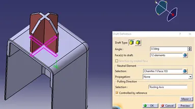
0.5 draft is applied to the locator.
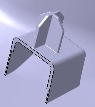
Once the doghouse and locator is assembled the part can be copied and translated to the opposite side by means of creating a plane in the middle.
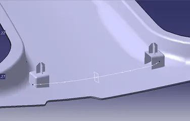
Next is thr rib creation a sketch is created with distance of 60mm from centre of doghouse once the sketch is done they are extruded.
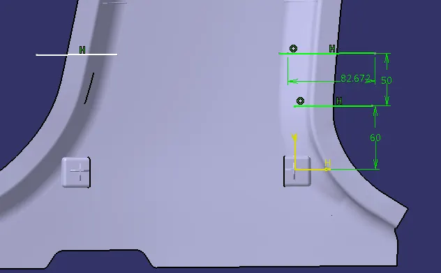
Once the Rib is created they are drafted with 0.5 deg draft and they are offseted to a distance of 50mm till the end of the flange surface.
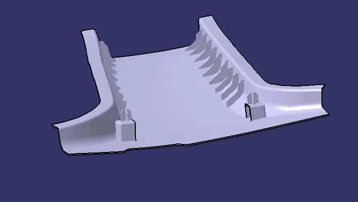
Same step is followed on either side and they are assembled with Paart body. Once the Part body is completed then they are subjected to draft analysis.
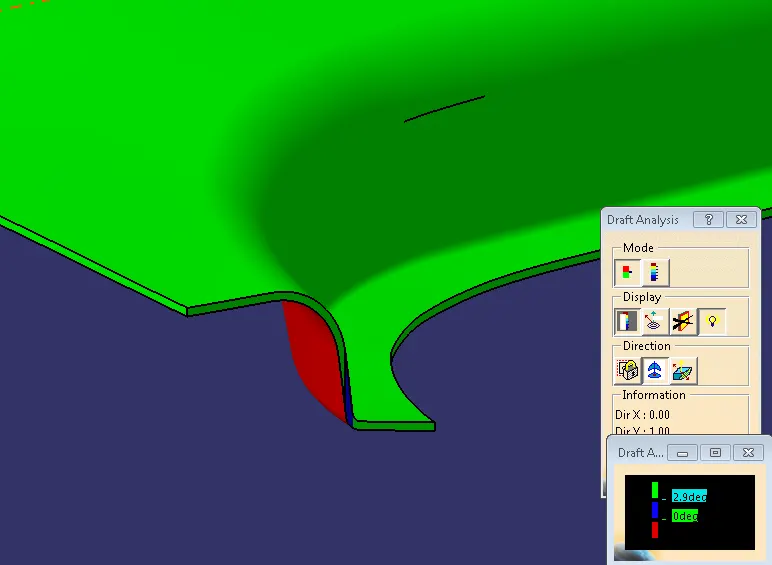
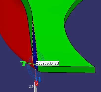
Draft analysis on the B pillar body shows that class a and c surface have a positive draft of 3 deg and the highlighted blue area have draft of 2.839 deg.
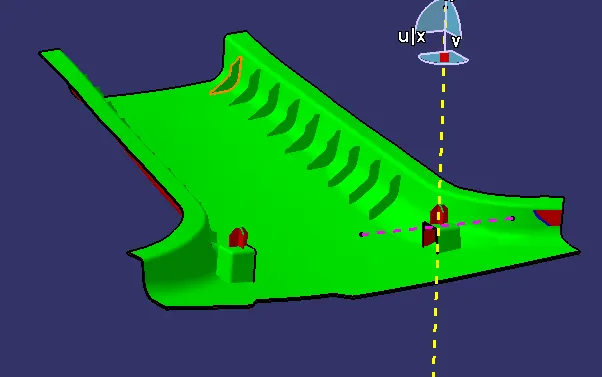
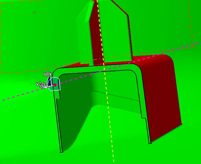
Draft analysis of class B surface and the Dog house via slider axis. For Doghouse the internal walls have a draft of 0.5 deg and the class b features such as the ribs are also drafted with 0.5 deg draft.
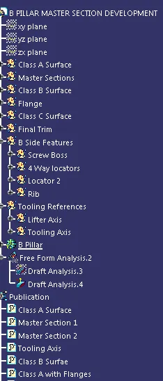
Tree Structure