Creating a B-pillar using Master Section Development.
AIM:
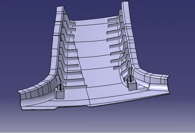
To create a tooling axis, extract B-surface and C surface from the given Class-A surface and create a 4-way locator on the dog house and ribs throughout the B-pillar. To perform draft analysis on a solid body, locators and the ribs created by the Class-A surface.
PROCEDURE:
Firstly, open the model using the open command.
TOOLING AXIS:
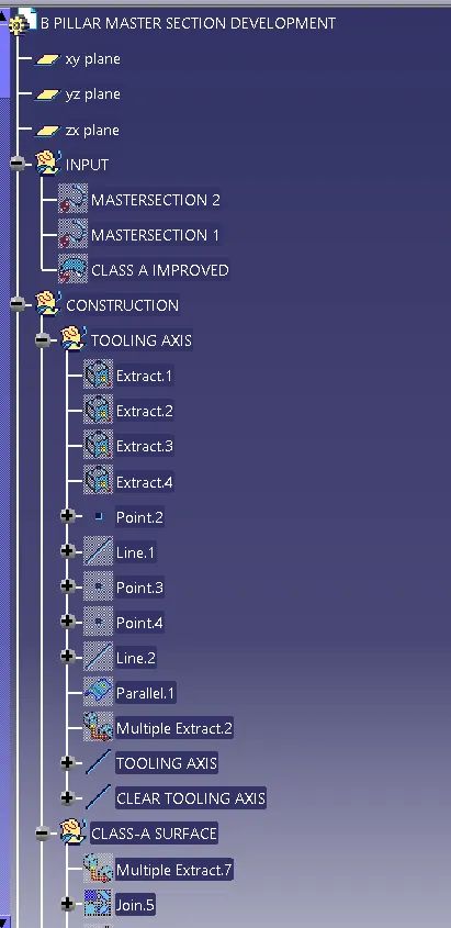
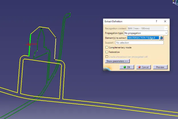
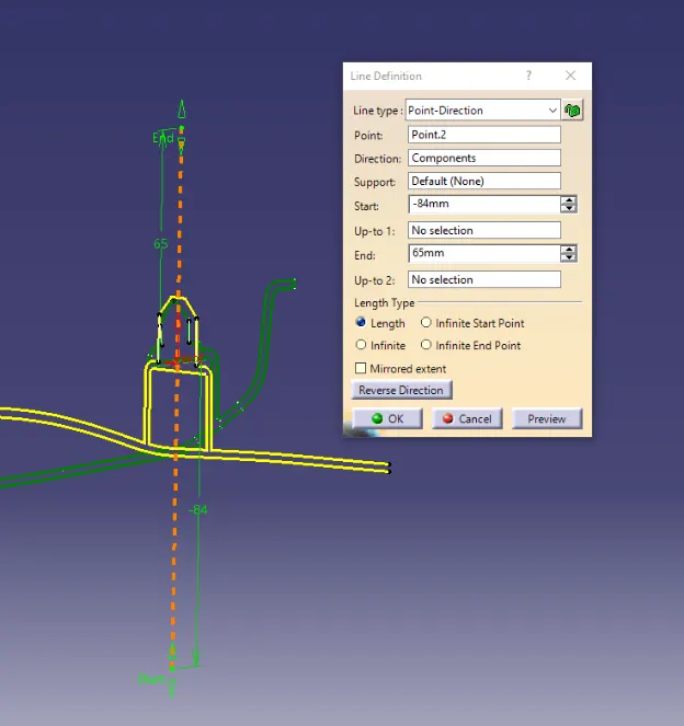
Extract lines on the YZ plane by projecting the master-section on the plane.
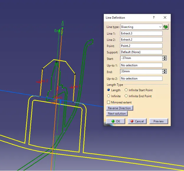
Create a bisecting line using the extracted lines
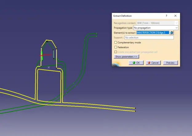
Similarly, extract lines on the ZX surface by projecting the master-section of class-A surface.
Create a bisecting line using the extracted one’s.
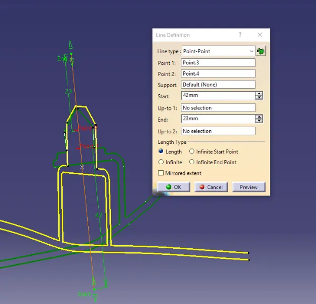
Now, create a bisect line using YZ and ZX lines and rename it as Tooling axis.
CLASS-B SURFACE:
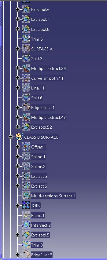
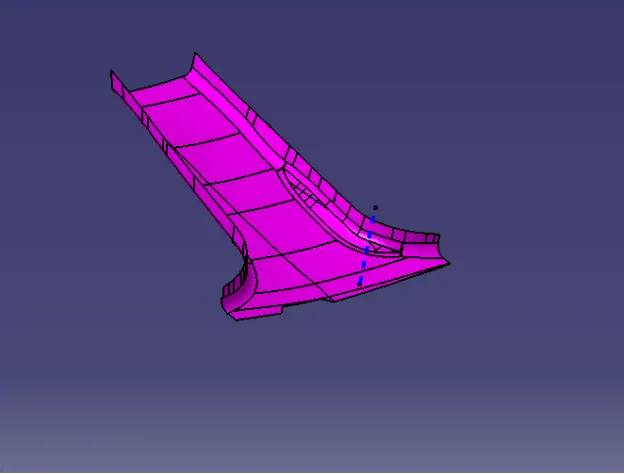
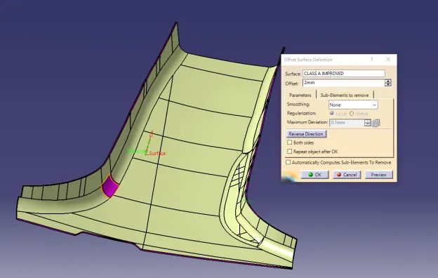
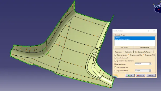
To create-B surface, first offset the class-A surface to 2mm.
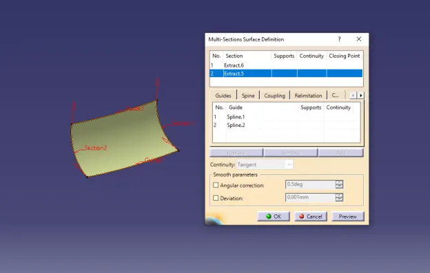
During offset the fillet patch gets deleted so create it using a multi section.
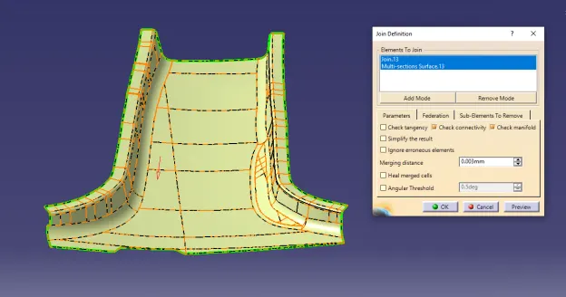
Now join the patch of the fillet with the offsetted surface.
The B- surface is created but they are outward flanges attached to the B-surface.
FLANGE:
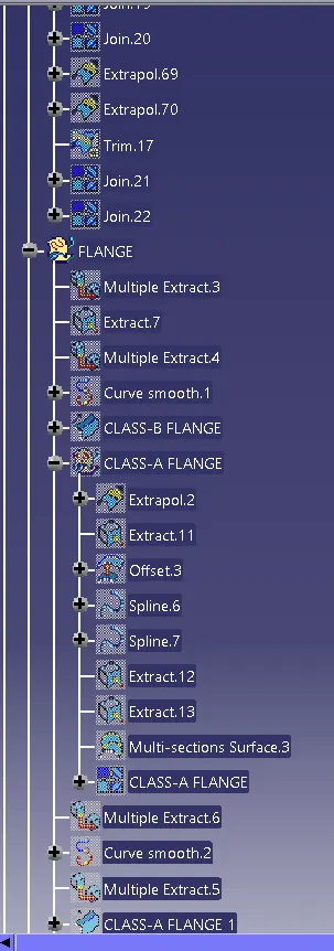
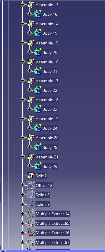
To create a flange, extract the side wall of the B-pillar and multi-extract the upper boundary and give a smooth curve to it.
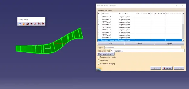
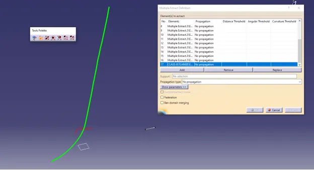
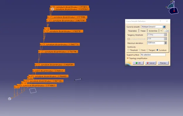
Now use a swept command with a reference surface at an angle of 101deg measured by the given master-section.
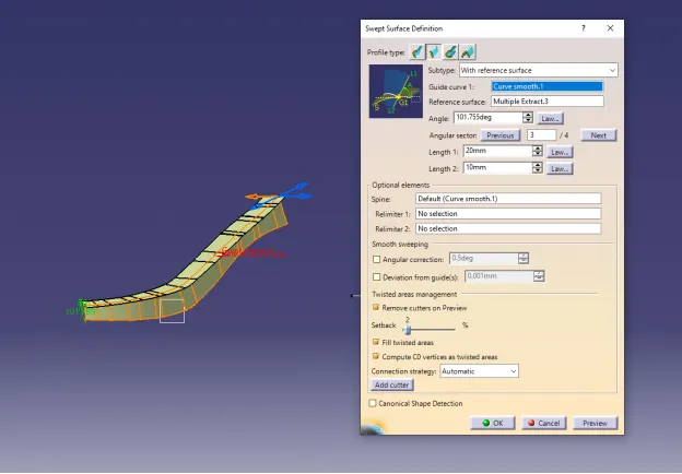
Similarly, create a flange on the other side. Extract the side wall of the B-pillar and multi-extract the upper boundary and give a smooth curve to it.
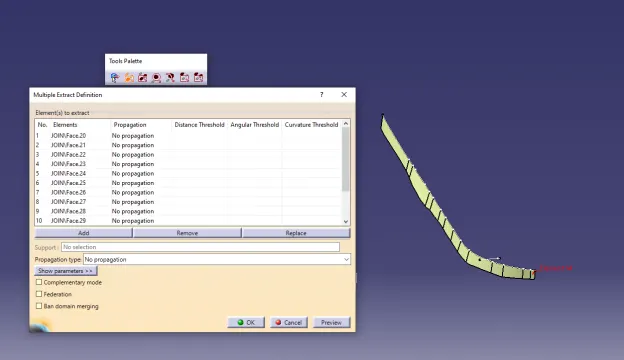
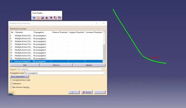
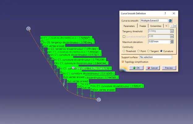
Now use a swept command with a reference surface at an angle of 85deg measured by the given master-section.
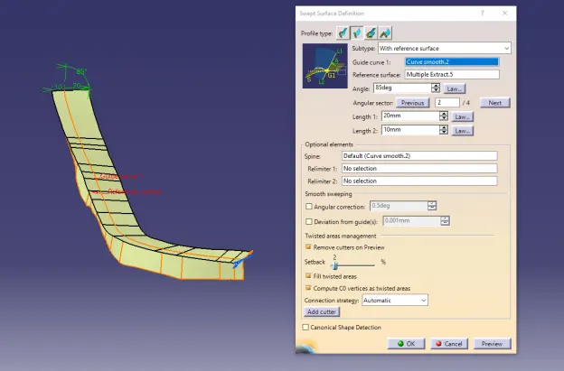
Now attach the flanges to the B-surface.
CLASS-A FLANGES:
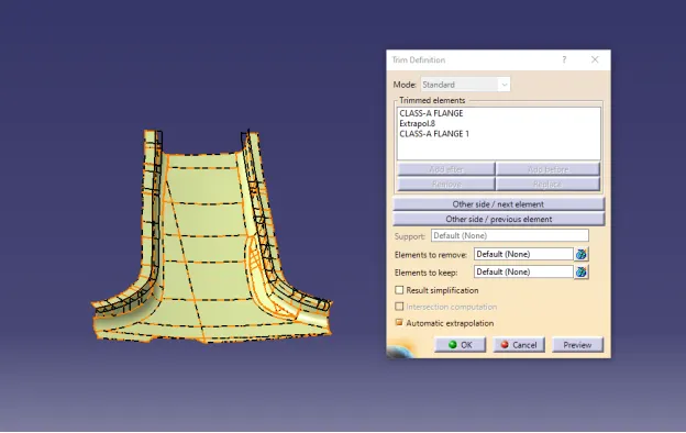
To create the flanges, offset the B-surface flanges and trim with the A-surface.
CLASS-C SURFACE:
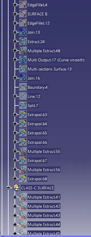
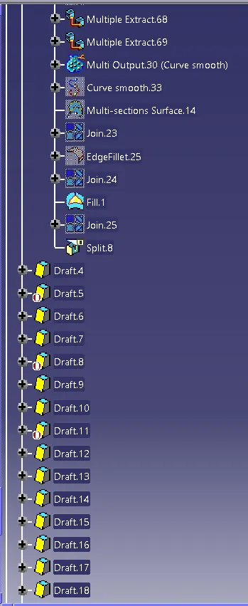
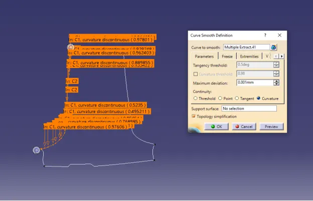
To create a Class-C surface, use the multi extract command and extract the boundaries of Class-A surface.
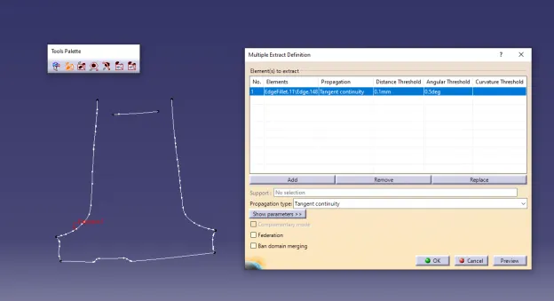
Smooth the extracted curve using a smooth curve command.
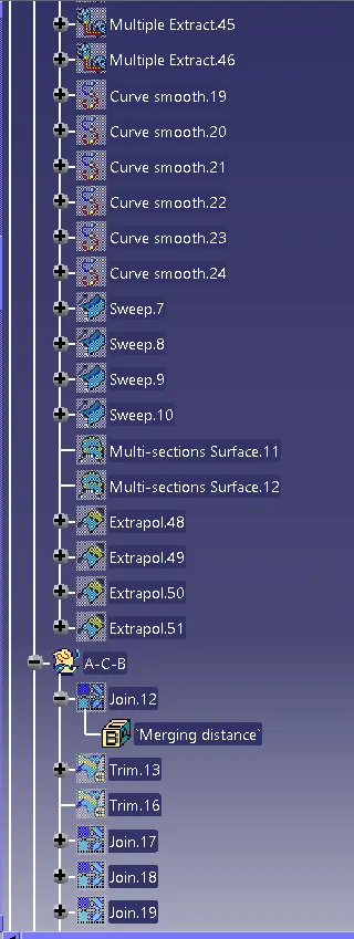
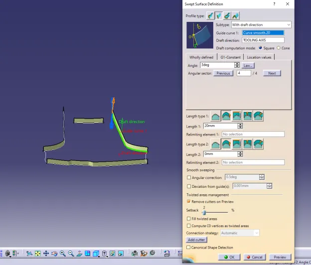
Then use the sweep command to create a surface using with draft direction option.
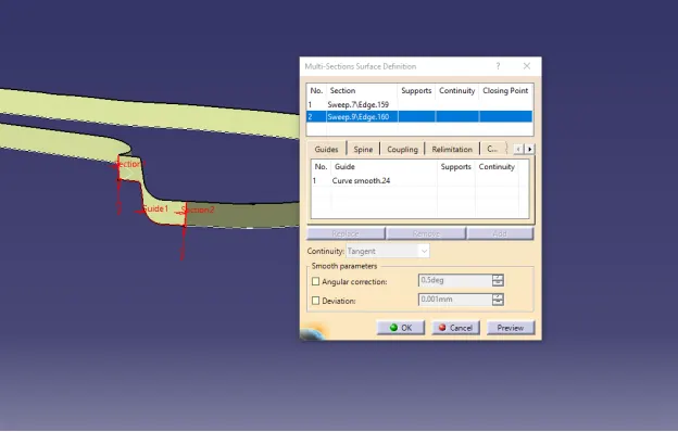
At the corners it a complicated curve so use multi section command to create surface.
ATTACHING A-C-B:
After all the surfaces are created Trim the Class-A and Class-C surfaces.
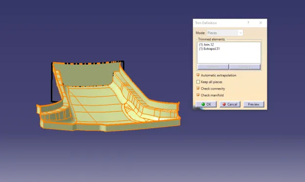
Now, trim it with a Class-B surface.
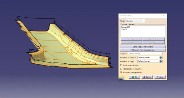
Now, Check for the boundaries if there’s any boundary close it.
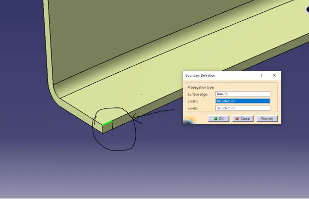
Use a join option and sub-element to remove than extrapolate the surface and trim them.
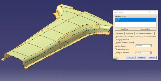
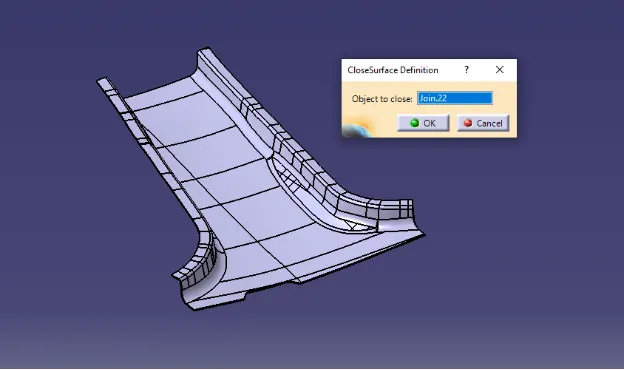
Now join it with Close surface.
CREATING SOLID BODY:
Now, create a part body and select a closed solid.
DOG HOUSE:
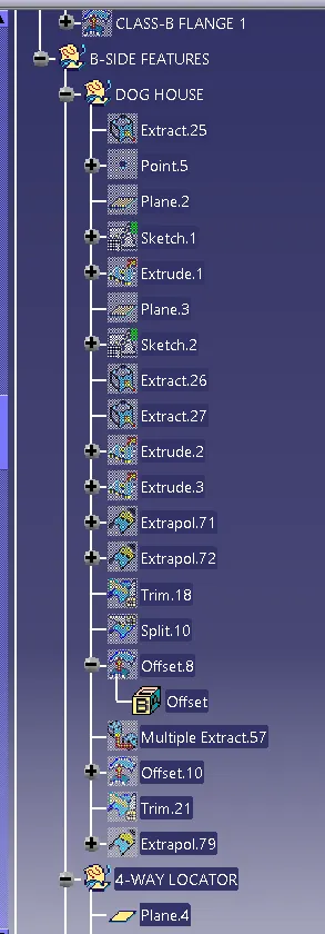
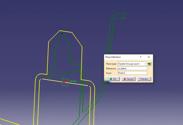
To create a dog house, offset a plane on the point create in the middle of master-section
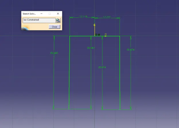
Create a sketch, using the plane and master-section 1 lines projected on the sketch and Iso-constraint it.
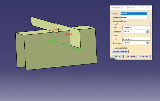
Extrude the sketch and create another XY-plane using master-section 2 and create a sketch constraint it.
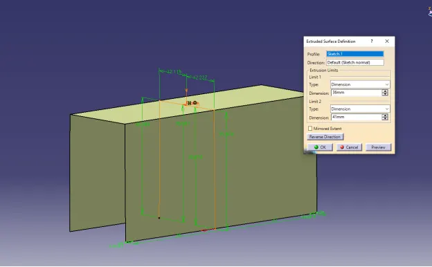
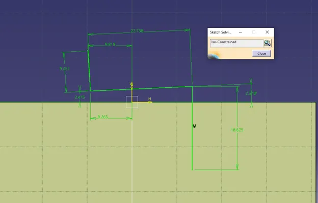
Similarly, extrude it and trim with the previous extrude with a backward surface.
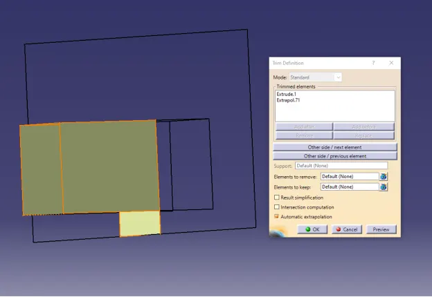
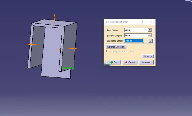
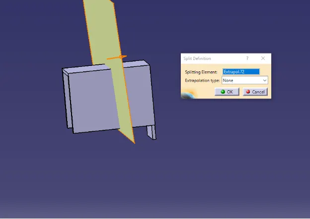
Now thicken the surface and split it with the front extruded surface.
Now, create a sink mark remover extract the side walls and offset to 40% of thickness i.e 1.2mm.
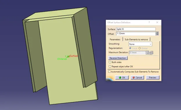
Now, offset the class-A surface to 9mm and trim it.
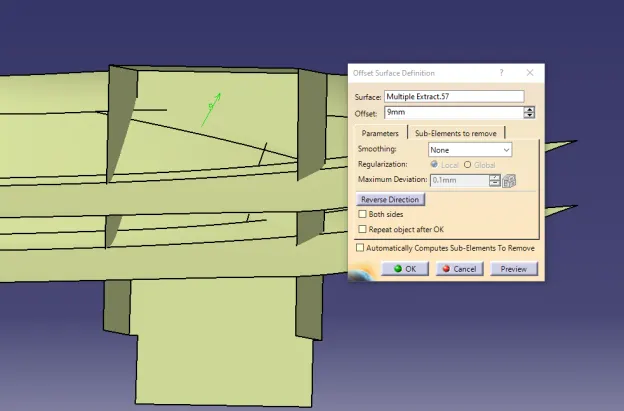
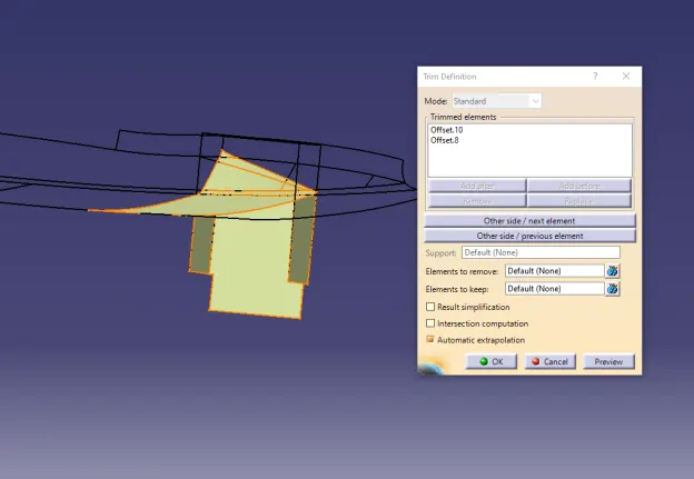
Now, split it with the solid body.
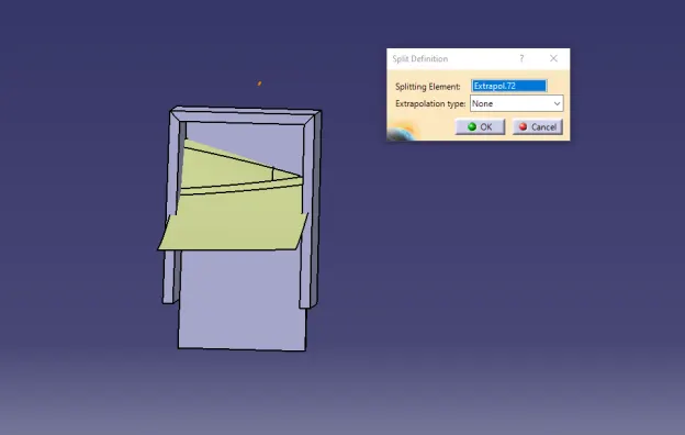
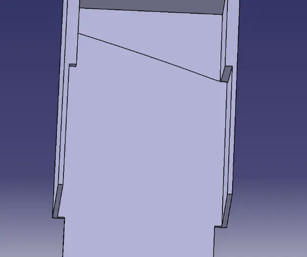
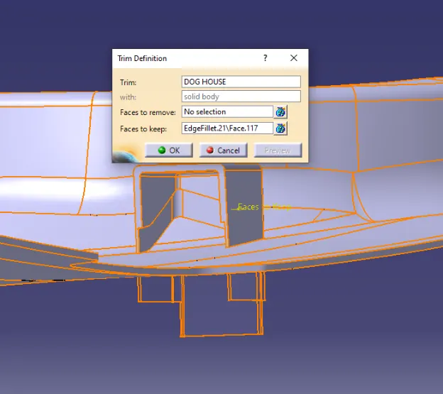
Now, union trim it with the B- pillar solid body.
LOCATORS:
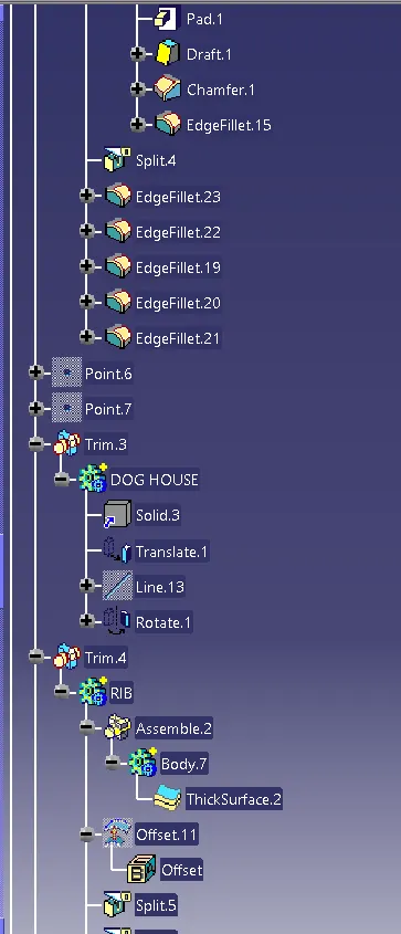
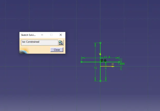
To create a 4-way locator, create a sketch using master-section line projection and Iso-constraint it.
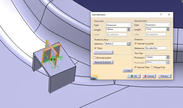
Goto part design creates a part body and pad with neutral fibre 1.5mm thickness.
Now chamfer, draft and give edge fillets to the locator.
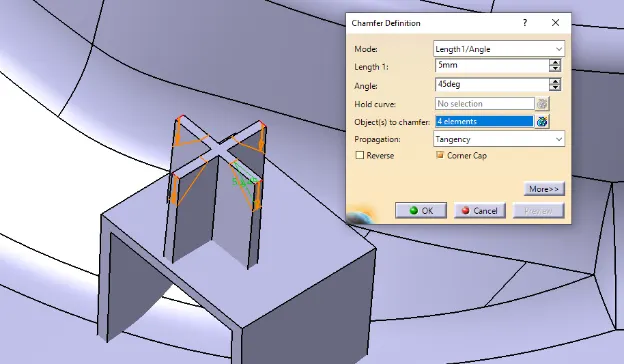
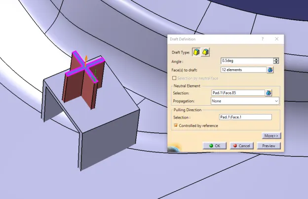
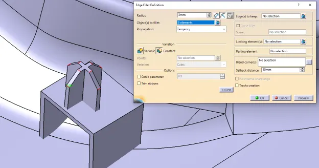
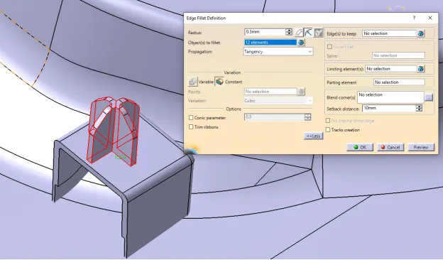
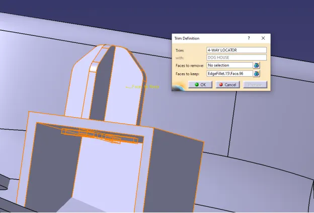
Now, union trim it with the dog house.
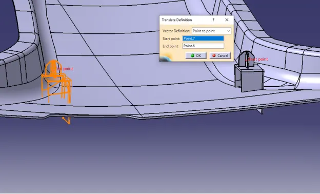
Similarly, copy the locator on dog house and paste special with a link then translate it.
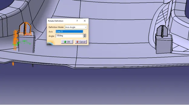
Rotate it 180deg.
RIBS:
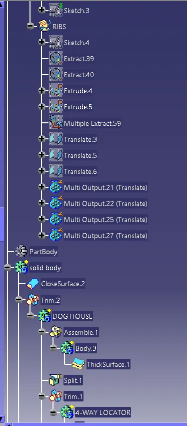
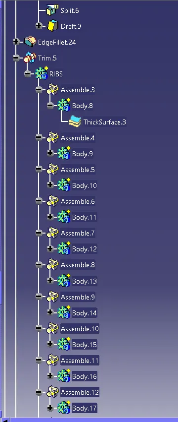
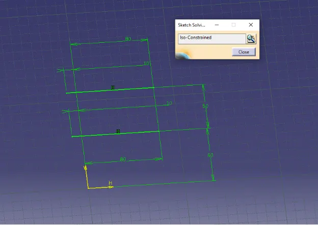
To create the Ribs, Go to the Sketcher workbench and draw a straight line on the face you want to create a rib and constraint it.
Exit the Sketcher workbench and Open the Generative shape design and extrude the surface. Create a Solid component.
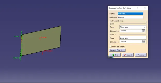
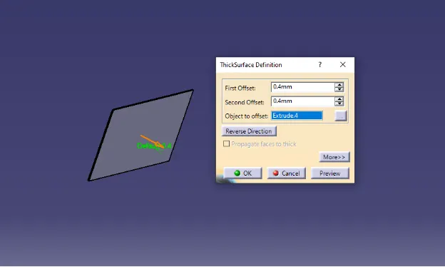
Offset the Class-B surface to 5mm and split it to cut the rib surface.
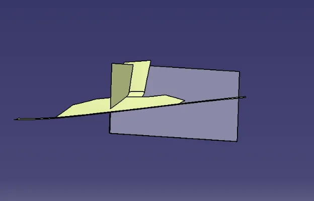
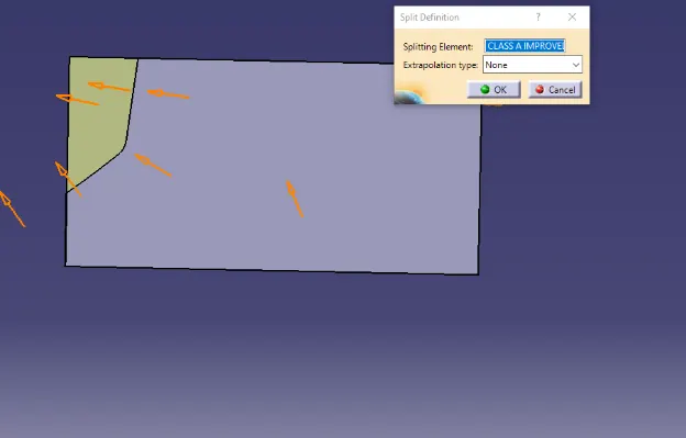
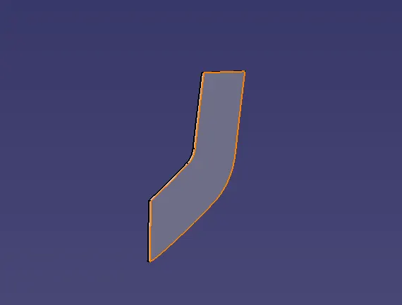
Now, union trim the rib to get the final Rib structure by removing the unnecessary faces.
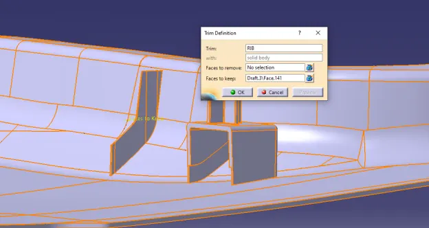
Select the Points repetition option to create the Points on the extracted line and give the offset distance as 50 and select the curve line.
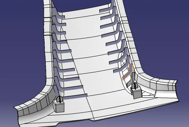
Now copy the Part body and paste it on the main Tree Structure. Use the Translate option to move the copied rib part body from the starting point to the ending 50mm point. Click Ok and Union trim the model. Follow the above steps repeatedly to create the ribs on both sides.
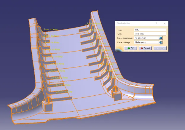
The Final Solid component is created.
DRAFT ANALYSIS:
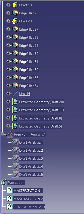
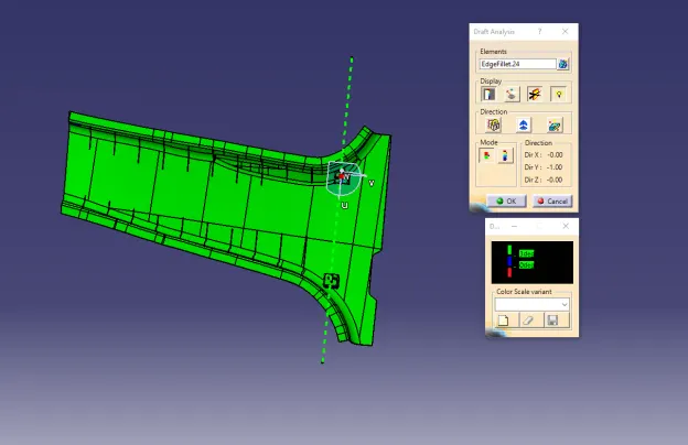
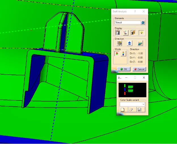
Draft Analysis is done on the solid body.
After the Tooling axis is created, the Draft analysis is done on the surface.
Select the Elements as the Class A Model and the Direction as the Tooling Axis using the Compass option to define a new
the direction of the draft.
Click OK to check if all the surface comes under the limits of 0 to 3 degrees.
If the draft is more than 3 Degree then the surface will be shown as green.
RESULT:
The Class B & C surfaces have been created using tooling axis, 4-way locator on dog house, ribs and drafting analysis are done on the solid body created by A, B and C surfaces of B-pillar.
TREE STRUCTURE: