Week 9 - Project - A pillar Design with Master Section
AIM
To study the given master section and create the B side and a dog house on it.
REPORT
1. Creation of tooling axis
- Check weather the given A surface is ok and without any patches using the boundary option or join option.
- Once that is checked, study the master section given.
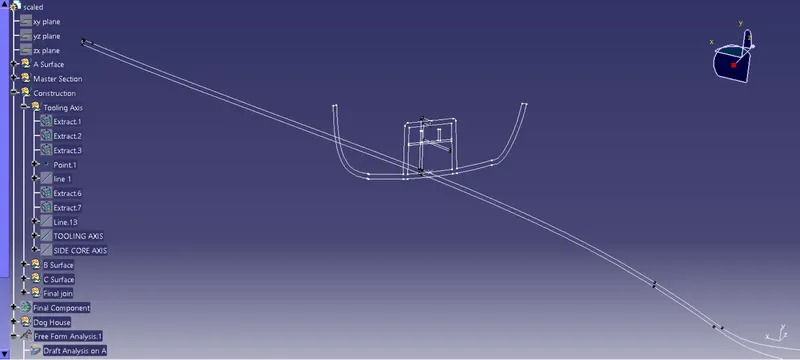
- Select all the 4 vertical lines of the dog house master secton.
- Using points created between two points options create a point in the middle of any two lines
- Using bisecting line method, create a line passing through that point using two opposite facing lines.
- Using the other opposite facing lines create another bisecting line through that point.
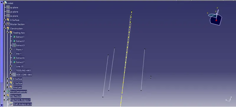
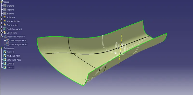
- Now create a bisecting line bisecting these two lines which is our tooling axis.
2. Draft analysis on class A
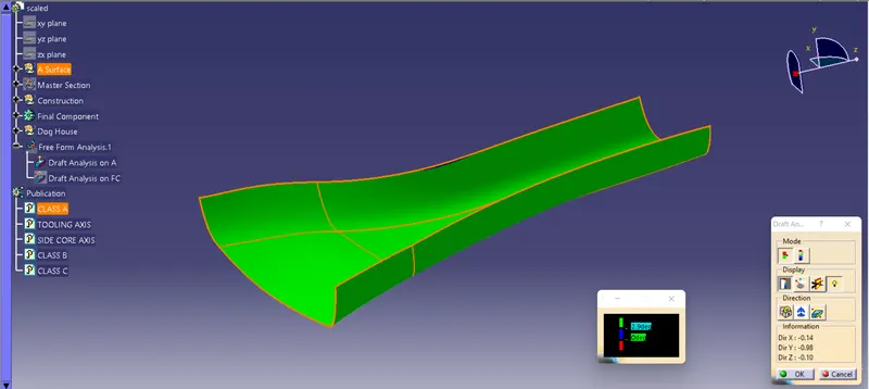
- Once the tooling axis is created, we run the draft analysis on A surface.
- The compass is placed on the tooling axis and the analysis is run.
- As you can see the surface clears the draft analysis proving that the tooling axis is correct.
3. Creation of B surface
- Measure the master section to find out the thickness.
- Offset the class A surface to 2.5 mm inside.
- Identify the patches formed.
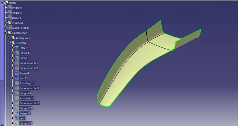
- Fix the patch using sweep command explicit option.
- Join the sweep with the off setted surface to form the B surface.
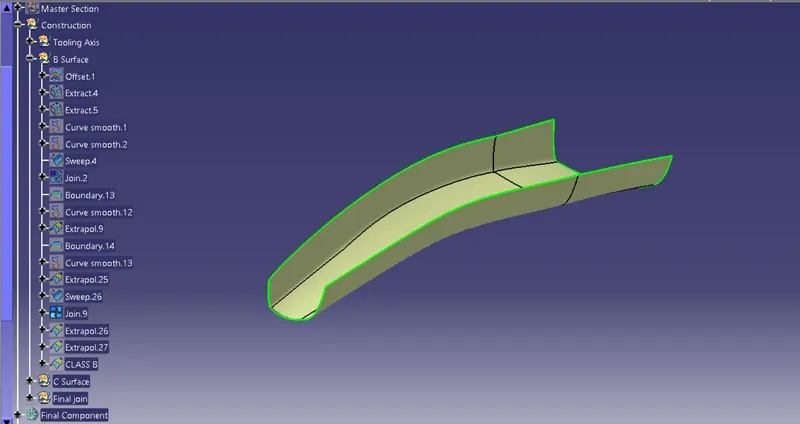
4. Creation of C Surface
- Use sweep command to create the C surface.
- Select the class A surface, and using sweep command sweep the edges of the class A surface 90 degree and 3 degrees according to the design of the surface.
- Join or trim all these multiple sweeps created to form a single C Surface.
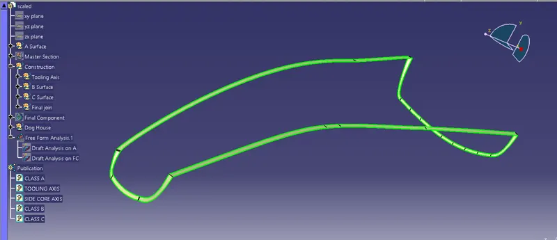
5. Final join
- First join the Class A and Class C together.
- Then trim that join using B surface to get our final component.
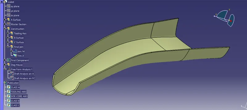
6. Creation of closed surface component
- Once the final join is done, go to part design and select closed surface option.
- Select the trim.
- The closed surface component is created as a part body
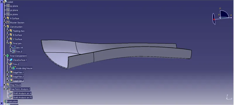
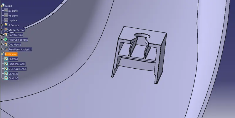
7. Creation of the Dog house
- First create a plane on the inner walls of the dog house section using plane creation by through two lines option.
- Create a sketch of the outer walls of the dog house by creating a rectangle around the dog house section and then coinciding the sketch with them.
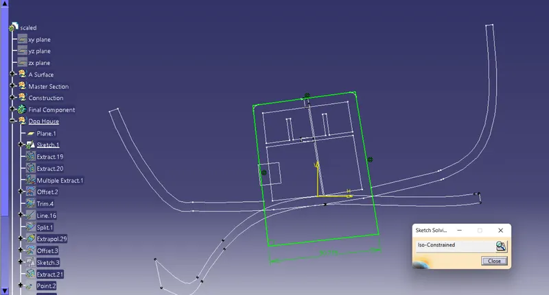
- Define the work in a new body and open part design workbench.
- Pad the sketch to both sides by measuring the master section.
- Shell the block on one side for 2.5mm.
- Give a draft of .5 degree to the outer walls.
- Then create a side core axis using an extract from the outer wall of the dog house and creating a line normal to that extract passing through the point.
- Give draft of 0.5 degrees to the inner region of the dog house using the side core axis.
- Give appropriate thickness to the dog house where it contacts the backside of the surface.
- Doghouse wall thickness at the intersection of the part wall should be 40% or less than the main wall stock.
- The height of that thickness should be between 3.0 – 6.0 mm
- For that we extract the inner walls of the dog house using multiple extract.
- We then extract the base of the final join surface.
- We offset that to around 5mm in the upward direction.
- We trim this with the multiple extract.
- Cut the extra portion using line and split
- Extrapolate the trim surface.
- Then offset the extrapolated surface outise by 1mm.
- Then we go the part design and use split to cut the padded body using this offset to get the thickness.
- Apply draft of 0.5 degree to that surface using side core axis.
- Then we create a sketch for the upper rib of the dog house following the same procedures as we did before.
- Using profile line we draw lines emulating the rib design and then coincides them together to get the required shape.
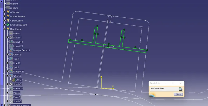
- Then again we pad that rib in a new body.
- This body gets union trimmed with the dog house body.
- Then we create a sketch for the pocket design on top of the dog house.
- We use sketch to draw the shape of that pocket using the given data.
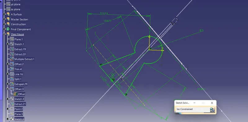
- We use pocket option to create this hole.
- We apply draft of 1.5 degree to this using tooling axis.
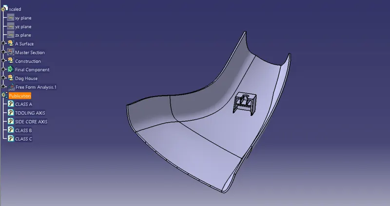
- We then union trim the dog house body with the main body.
- We apply fillets whereever it feels necessary.
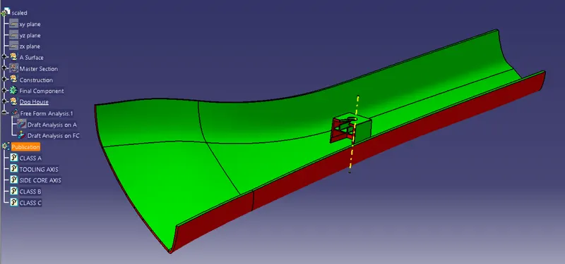
8. Draft Analysis on the final body
- The compass is placed on the tooling axis and the analysis is run.
- As you can see the surface clears the draft analysis by clearing every surface.
RESULTS
1. ISOMETRIC VIEW
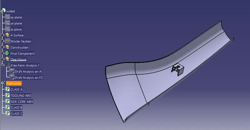
2. FRONT VIEW
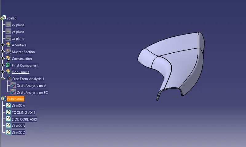
3. SIDE VIEW
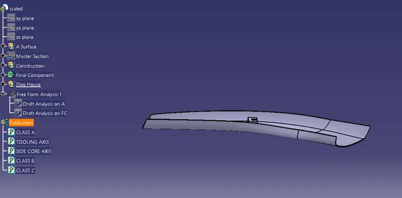
4. TOP VIEW
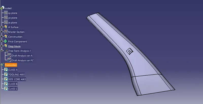
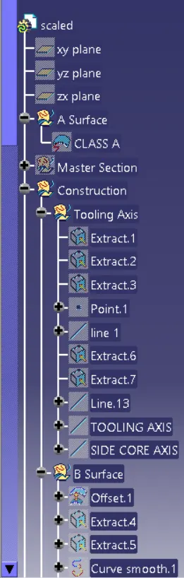
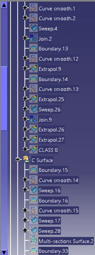
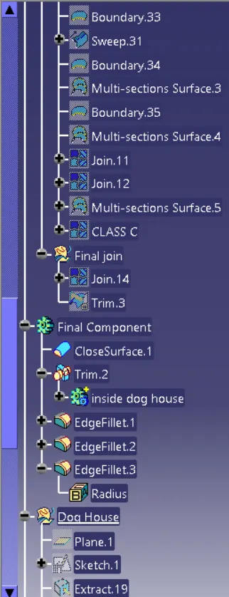
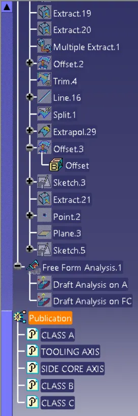
TREE STRUCTURE