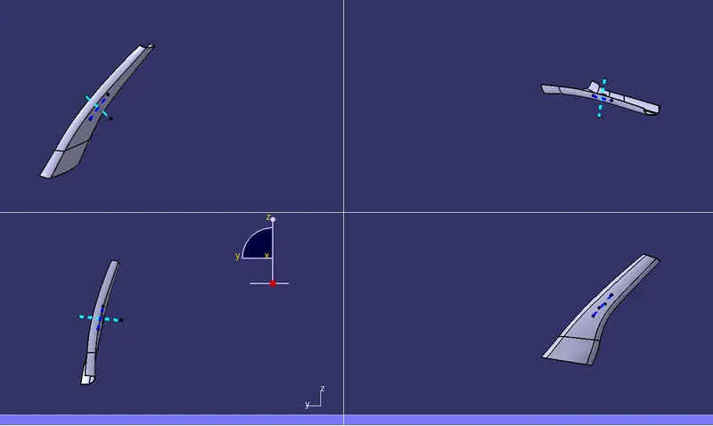
Week 9 - Project - A pillar Design with Master Section
REPORT:
AIM: TO CREATE CLASS B AND CLASS C SURFACE ALONG THE MASTERSECTION AND CREATING THE ENGINEERING FEATURES
PROCEDURE: First we will receive the Class A and with along master section as an input
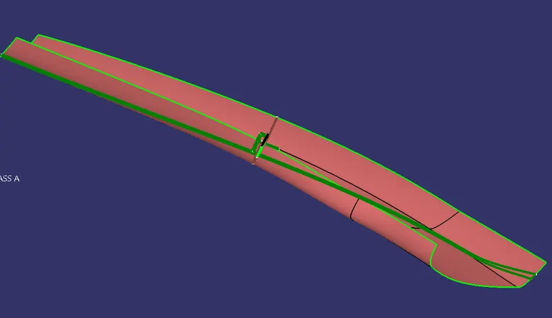
from this output we have to make class class B surface and Class C surface And then and then the engineering features Before creating all these things we have to we have to create a proper tooling access for this component For creating tooling access we have master section from the master section we can use the bisecting line method and we can create a tooling axis.
first we will extract the the four lines of the massive section That is nothing but the outer lines of the master section And we will recieve the output as follows:
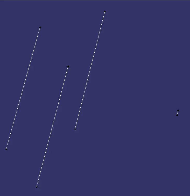
after getting the output as above we have to extract the downside points of the any two parallel line and we have to create the midpoint using extracted points and we have to isolate all the points.after isolating the points we have to create a bisecting line with the help of any two parallel lines and that mid point after getting the bisecting line we have to create another bisecting line using other two parallel lines but with the same mid point.
after getting both bisecting line we have to create another bisecting line with the help of the other two bisected lines and the final bisecting line will be our tooling axis. the output will be as follows:
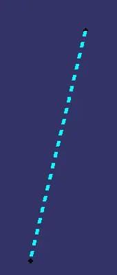
after getting the tooloing axis we have to create the B surface for the component.
for creating the B surface we will offset the entire class A to the required direction and required distance with the reference of master section and we will get the output as follows:
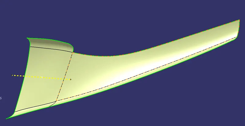
but the output which we recieved is not correct beacuse one of the patch from the class A is completely missing.
to create that patch we will use sweep command to create that patch .
in the sweep command first profile type.after using the sweep we will get the output as follows:
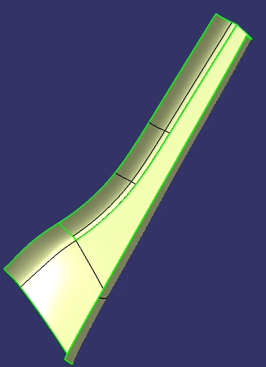
but the output which we recieved is having two surface to make it as a single suface we will use join command and make it as asingle component and the our class B is ready.
after getting the class B we have to create the class C surface.
to create the class C surface we will use sweep command and we will create the c surface the output will be as follows:
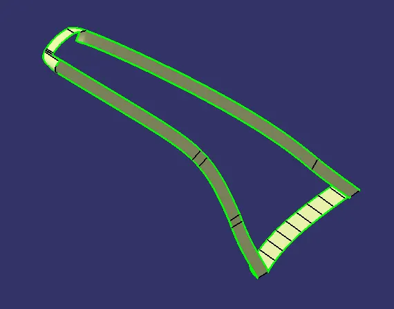
after getting the C surface we have to join it with the class A surface and our output will be as follws:
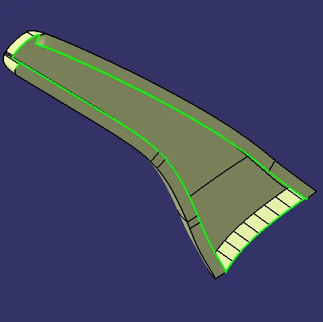
after getting the join of class A and class C we have to trim class B with the join of class A nad class C and we will recieve the output as follows:
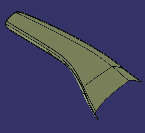
to ensure that our body is closed we have to create a boundary on it if the boundary is not creating then our surface is closed.but the closed surface which we got is hallow inside but we need it as a solid part. to make it as a solid part we have to got part design and then we have to use the close surface command to close the surface and make it as a solid part. and our output will be as follows:
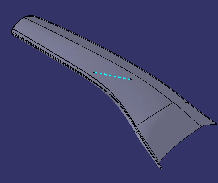
after getting the closed body we have to create the engineering features with respect to master section.
the master section which we got is look like dog house.
to create the dog house first we have to create a proper direction plane and point and then we need to do position sketch and we have to padd it and we will recieve the output as follows:
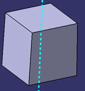
after padding it we have to use the shell command to make the surface hallow on two side. Before doing the shell we have to maesure the thickkness of the dog house with the help of master section.the dog bhouse thickkness master section which we recieved is 2.5 mm thickness so we shelled it for 2.5mm thickkness.
the output will be as follows:
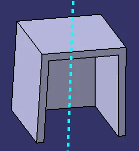
after getting the shell the outer part of the dog house is already drafted in mastrer section but the inner part is not drafted do we will draft the inner faces to a minimum draft of 0.5degree. but for drafting the inner faces we want an separate side core tooling axis .
CREATION OF SIDE CORE TOOLING AXIS:
to create the side core tooling axis we have to extaract the back face of the dog house and we have to create the line with reference to that extract and the point of main tooling axis and we will receve the output as follows:
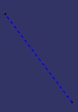
but for this line we will use normal to surface method line. After getting the line we eill name it as side core tooling axis.
after getting the side core tooling axis we have to draft the inner faces of the dog house for 0.5 degrees using side core tooling axis.
after drafting the inner face we have to create the C surface of the dog house to avoid sink marks.
CREATION OF LOWER SURFACE FOR DOG HOUSE:
the lower can be created by extracting the inner faces and extracting the base and offsetting it to the 40% of the wall thickness and offsetting the base to a 3mm to6mm so we offsetted the base to 4 mm and we have to trim the offsetted base with the offsetted inner extract and we will recieve the output as follows:
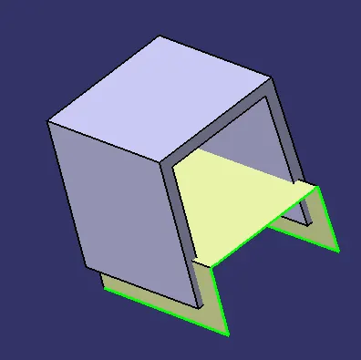
after getting the output as above we have to split the surface with dog house in the part design and we will recieve the out put as follows:
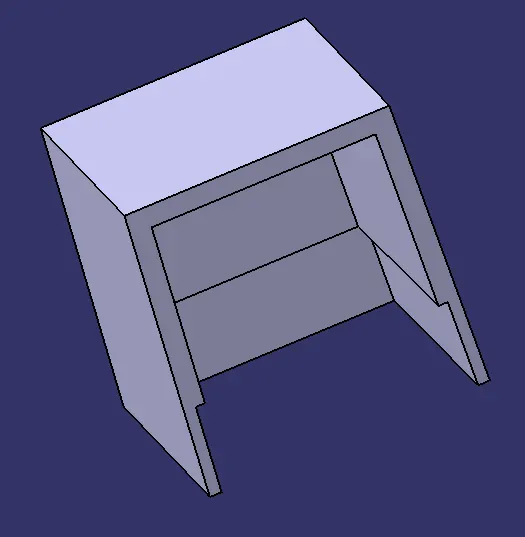
after getting the lower surface we have to create the ribs which is there in the master section.
CREATION OF RIBS IN DOG HOUSE:
for creating the ribs we will use the same plane and point which we used for creation of dog house and we will make the sketch of the ribs as per mastersection and then we will pad it and we will recieve the output as follows:
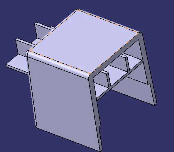
here the ribs are extended beyond the dog house to clear that we can union trim them with dog house and after that we have to make the hole on the top of the dog house.
As per the given dimension the circle hole is 5 mm radius and the the line is 30degree from the centre,so to create this hole sketch first we have to create a point on the top of the dog house and a plane then we can do the position sketch on that plane and point and then we will extrude it and then later we will split it in the part design
and then we will give the fillets the outer fillet of the dog house is 1.5 radius and the inner fillet value is not given in the master section so we will give the inner fillets as 0.25mm and we recieve the out put as follows:
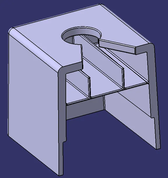
once if we get this output we will add it to the main part body instead of add i have union trimmed it with the main part body and our output will be as follows:
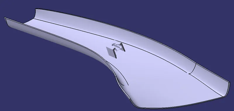
DRAFTING ANALYSIS:
DRAFTING ANALYSIS FOR CLASS A:
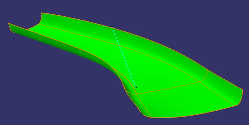
for doing draft analysis for given class A first we will go to
insert>analysis>feature draft analysis.
after selecting feature draft analysis we have place the compass in main tooling axis and the red dot on the class A and then our output will be as above.
DRAFT ANALYSIS FOR PART BODY:
for doing the draft analysis for the first pat body we will follow the same rules which we followed in the class A surface and our output will be as follows:
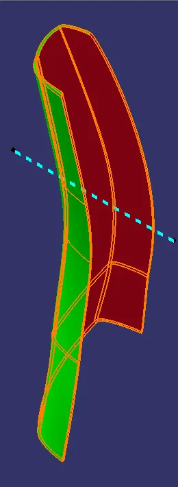
DRAFT ANALYSIS FOR DOG HOUSE OUTSIDE:
doing draft analysis for outside of the dog house is can be done by main tooling axis only and the same rules will be followed here also but the drafting angle should be 1.5 degreee minimum. our output will be as follows:
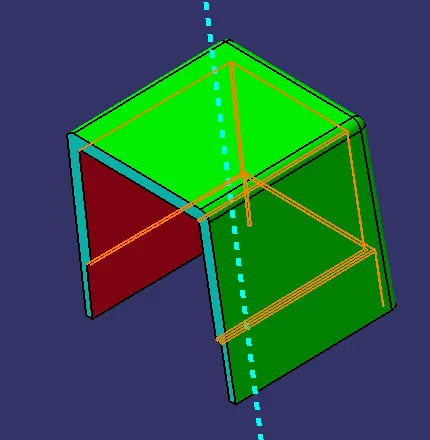
DRAFT ANALYSIS FOR DOG HOUSE INSIDE:
performing draft analysis for inside will be done by side core tooling axis only and the same rules will be followed here also but the drafting angle should be 0.5 degreee minimum. our output will be as follows:
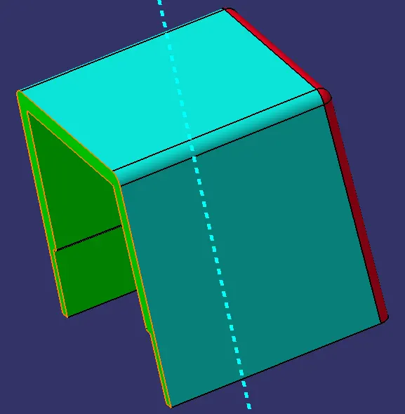
DRAFTING ANALYSIS ON THE RIBS:
performing draft analysis for RIBS will be done by side core tooling axis only and the same rules will be followed here also but the drafting angle should be 0.5 degreee minimum. our output will be as follows:
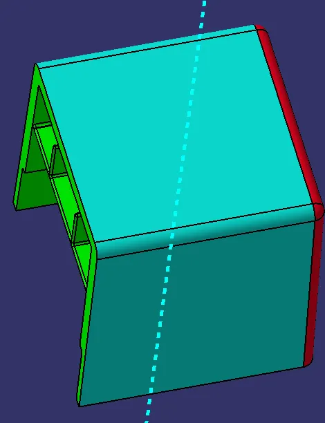
DRAFTING ANALYSIS ON FINAL PART BODY:
performing draft analysis is done by two tooling axis also first we will go with the side core tooling axis the side core tooling axis draft analysis on final part body output will be as follows:
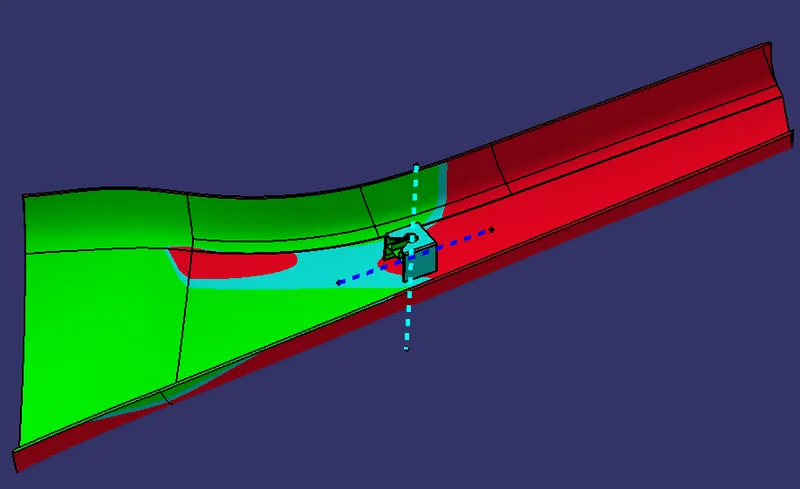
performinfg draft analysis on final part body using main tooling axis. the output will be as follows:
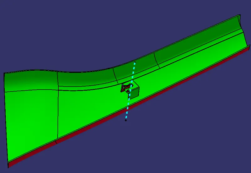
but here we have got the out put in two colours one is green colour at top and red colour at bottom which means the green colour is saying that the draft is more than 3 degree and the red colour at bottom is saying that the draft is less than 0degree once the drafting analysis is done our component is ready for manufacture.
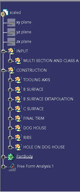
TREE STRUCTURE:
DIFFERENT VIEWS: