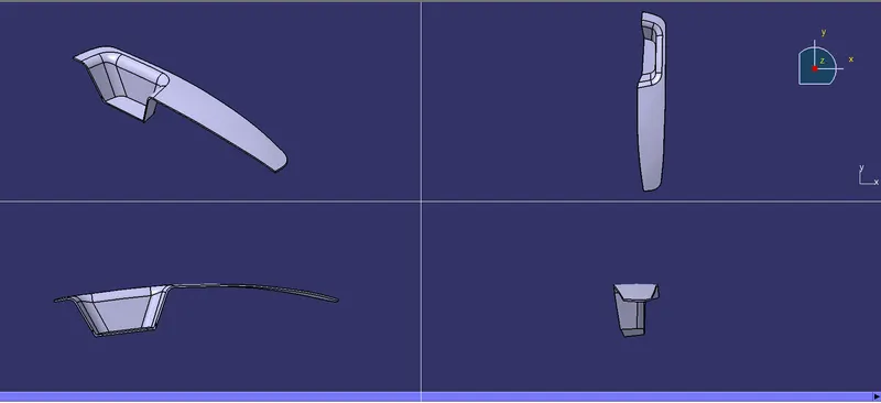
Week 8 - Challenge 2 - Switch Bezel Design
REPORT:
First we will recieve the class A surface as an input from the class A surface we have to create class B surface and class C surface
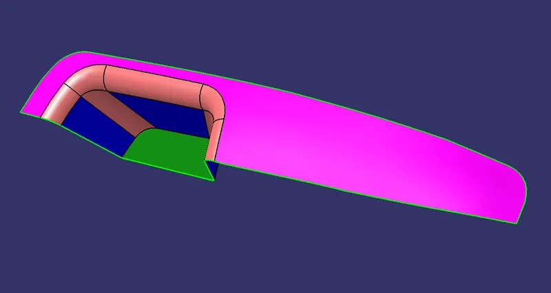 classs A surface.
to create the class B and class C surface we must create a tooling axis so that it can be manufactured easily with low cost.
Creating tooling axis:
the most of the best possible tooling axis are done in z direction.
To create a tooling axis first we have to create a bisecting line in y direction but before that we have to create a intersction along y direction to get the bisecting line
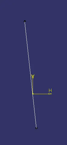
after getting the bisecting line on y direction we have to create a dummy geometry along x direction to get the bisecting line along x direction.
after getting the x direction and y direction bisecting lines using these two lines we have to create another bisecting line and that will be named as the tooling axis.
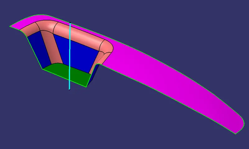 the tooling axis
after getting the tooling axis we have to check for drafting analysis on the class A surface so that we can thicken the component .
drafting analysis method:
Go to insert>anlysis>feature draft analysis
after clicking on On drafting analysis tool click on the composs tool and drag it to the tooling axis and lock the compass.
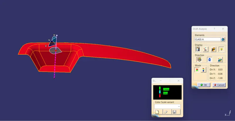
after locking the compass click the second option and display tool bar in draft analysis and then we have to check the drafting angle the minimum drafting angle should be 3 degree.
after completing the drafting analysis we have to create Class B surface by extracting each part of Class A surface by ignoring the filet and then we have to offset each part separately to the given direction and distance and untrim the extracted component and then and then we have to hide the extracted components and then extapolate the untrimmed component to a certain value by using point continuity method so that the components is fully extapolated by all the sides and then we have to use the trim command to trim the extra components.
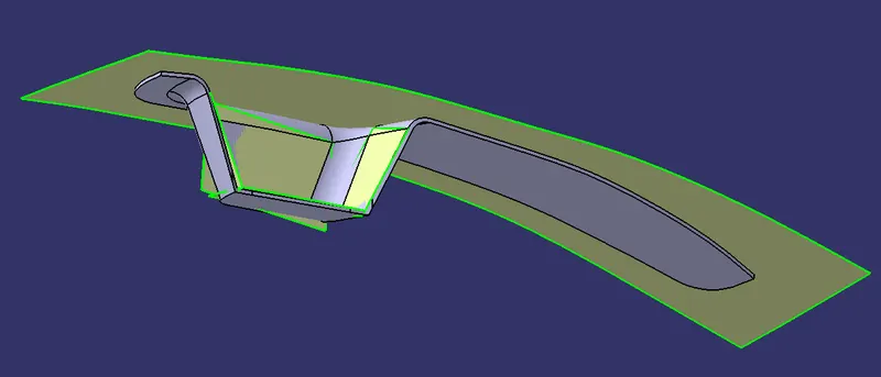 use the trim command to to trim the extra components.
after trimming the extra component we have to make fillets to their value and the thickness of the component for example if the fillet value is 15 and the thickness is 2.5 we have to give the fillet+ the thickness of the component 15+2.5=17.5 for inner surface if the component should be made in reverse direction(outside of class A) menas we have to do do the vice versa of it.
after doing all these we have to create class C surface by creating aboundary on the class A and then we have to use the sweep command
select sweep command>profiletype>choose the second type profile>sub type>with draft direction and choose the guide curve(boundary) and select the draft direction(tooling axis)and then give ok to a minimum health but ensure that the length should be more than the thickness of the component so that later we can trim it.
after sweeping the class C surface the class C surface will have some patches, to clear those patches we have to use the smoothcurve tool to make the patches invicible after doing the smooth curve use the trim command to join both class A and class C surface instead of using trim command we can use the join command but later it will create error to avoid those error we will use trim command.
after joining the class A and class C surface we will be getting the output as following:
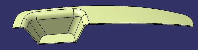
but after doing all these we have got only surface design which is hallow inside but we need a solid part so we go to part design and use the close body command to close the surface and make it a solidbody. the solid body is as follows:
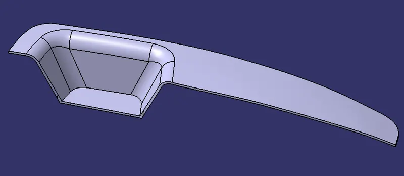
after finishing all these we have to check the draft analysis for the solid component
using feature dreft command and selectingthe compass tool in the direction tool bar and dragging it to the toooling axis and then locking it there and using the compass and checking the drafting angles.
the drafting anle should be maximun 3 degree and it should not increase more than that. Afterplacing the compass we get a red dot on the curserby clicking the red dot in the componentcolour will change and the top face becomes green colour and the bottom face becomes red colour.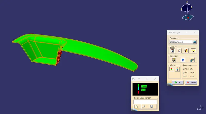
but before getting these colours the output will be like the following:
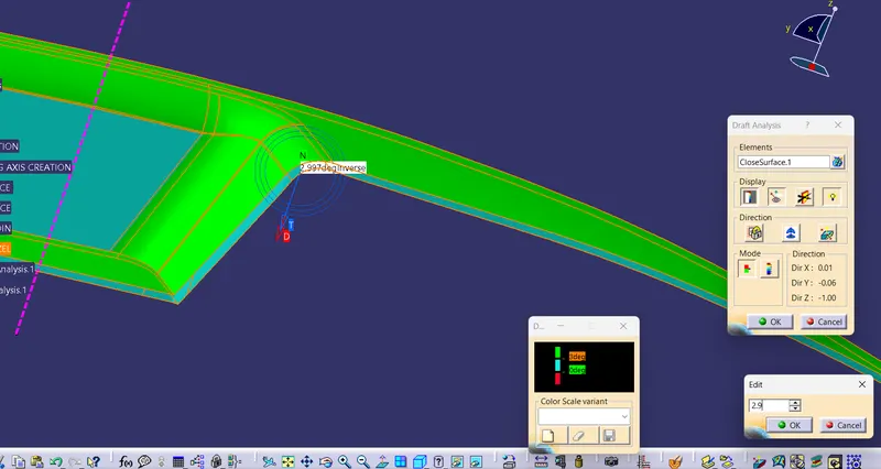
which means the blue colour is from 0 degree to 3degree but we want it to be 3 degree so we will change the drafting axis of x direction from 3 degree to 5 degree
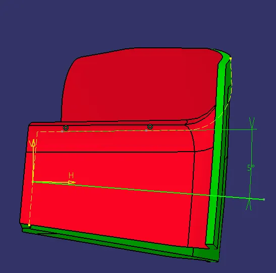 after doing this we will get the proper output as follows
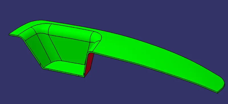
in which the green colour is saying that the draft is more than 2 degree and the bottom red colouyr is saying that the draft is less than 0 degree the red colour was not original before it was blue colour byt for our refence i have changed it to red colour so that we can find the easily that it has an negative value.
After finishing the checking of drafting analysis we have to hide the drafting anlysis and then our component is ready for manufacture.
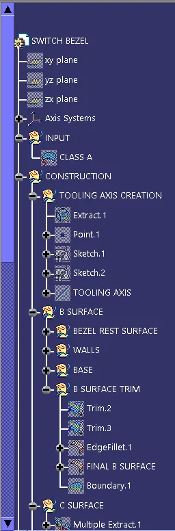
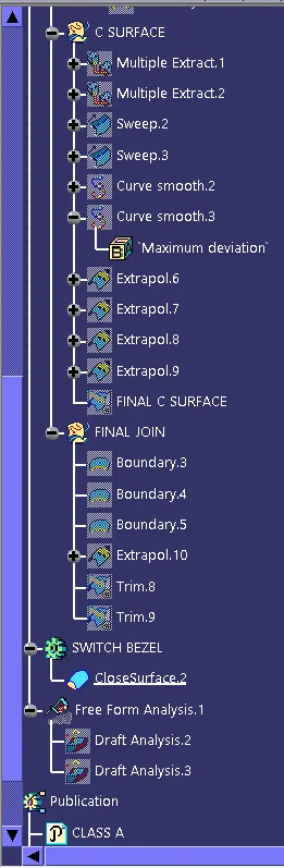
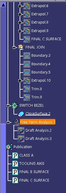
tree structure:
DIFFERENT VIEWS: