Week 8 - Challenge 4 - Bumper
REPORT:
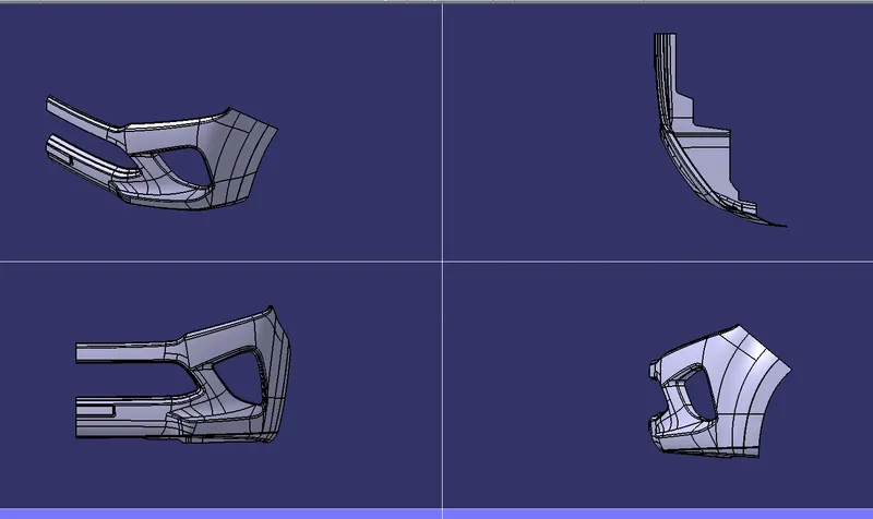
First we will recieve class A surface as an input from the class A surface we have to create class B surface and class C surface
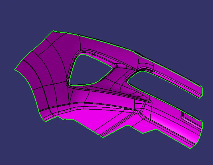 but the class A surface which we got is in the common colour but for our reference we changed the colour.to create the class be and class c surface we must and should create the tooling axis so that it can be mnufactured easily with low cost.
creating tooling axis:
the most possible tooling axis is z direction but in this component we have to take deep look and create a tooling axis. For the bumper we have to create the tooling axis in the direction where we can see all the patches.
after fixing the correct direction we have to extract the one patch of the component and then creating a point on it and then we have to create the tooling axis. The tooling axis is as follows:
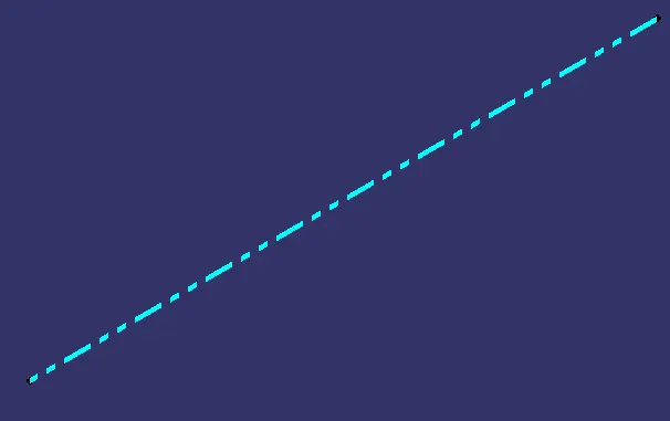
after creating the tooling axis we have to check the drafting analysis for class A surface. The checking of drafting analysis for the class A surface is as follows.
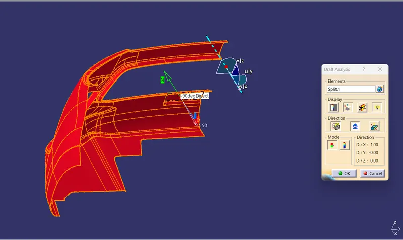
Drafting analysis method:
Go to insert>analysis> feature draft analysis
after clicking the drafting analysis tool click the compass tool and drag it to the tooling axis and lock the compass after locking the compassclick on the second option on display tool bar in draft anlysis and the we have to check the drafting angle the minimum drafting angle should be 3 degree.
After creating the tooling axis and the checking od drafting analysis we have to create the B surface for creating the B surface for the complex components like bumper we cant extract each one of them and and trim so we will offset the entire component.
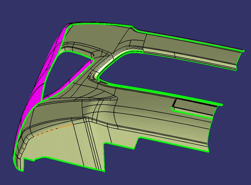
but after offsetting it we will be having the some gaps between the them
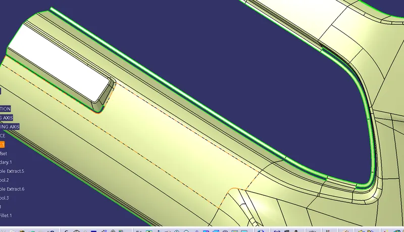
to clear the the gaps we have to multi extract them and then we have to extapolate them and we have to trim them
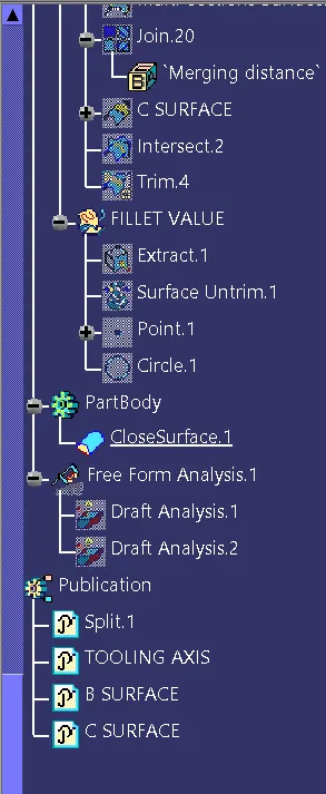
after trimming them we have to give the fillets also but finding the fillets value is complex in this component so we extract the fillet region and then we have to untrim them and then we have to create a point in the centre of it and then we have to create the three point circle using the vertex of the untrimmed components. the untrimmed circle is as follows:
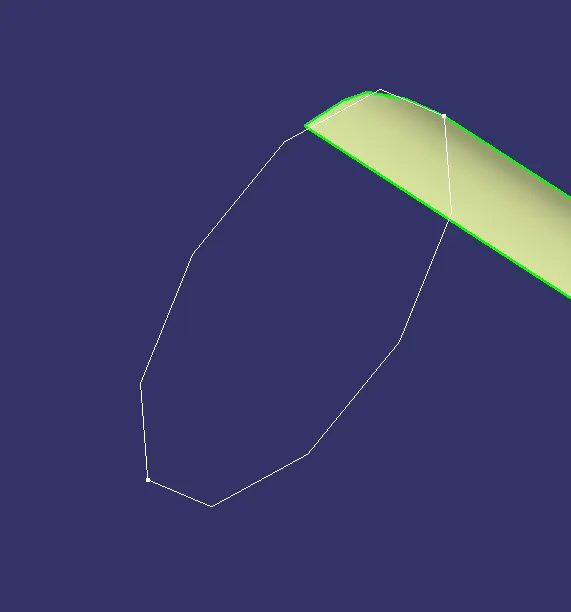
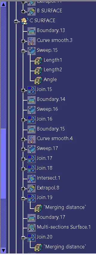
after clearing all the gaps and fillets we have to create the C surface. For creating the C surface we have shortcut to do it creating the boundary on a class A surface edge and then directly sweeping it with refrence to surface. we will get the out put as follows:
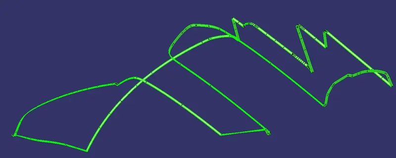 but here we will get a issue that the sweep is not proper
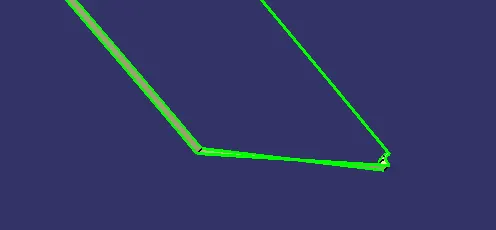 the sweep is cross over there.
to clear this issue we will use join command and then use remove the sub elements and remove the cross portion.And then we will create the boundary over the empty sace and then sweep it again and then it will come properly and then we will join them to the first sweep. the proper output is as follows:
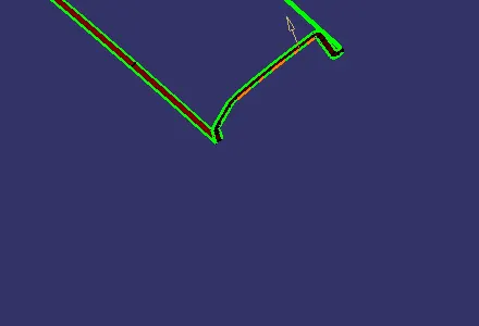
after creating the proper class C surafce we will join the class C surface with class A surface and then the output will be like this
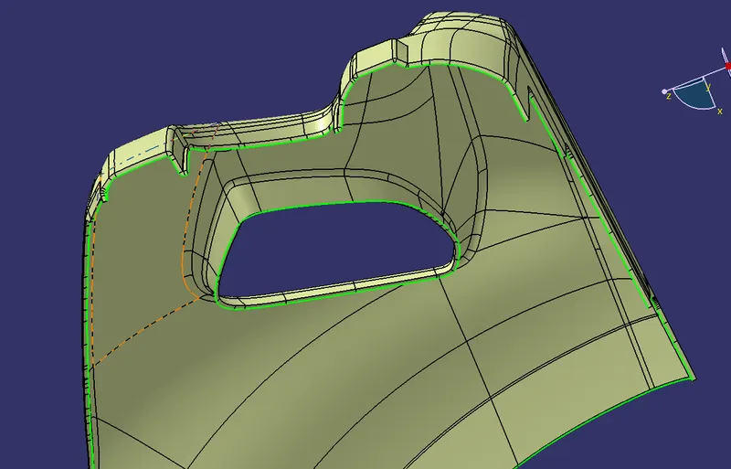
after getting the join of class A and class C we will trim the join of class A and class C with class B surface and we wiil get a closed surface such as follows.
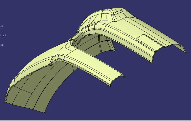
but the output which we got is hollow inside so we have ro make a solid part for making the solid part we will got part design and then we will use the close surface command to close the hallow surface and make it a solid body.
the solid body is as follows:
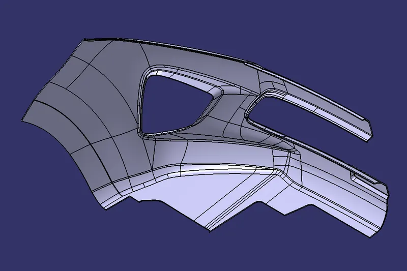 after getting the solid body we have check the drafting analysis for the solid component.
using the draft analysis command and then selecting the compass tool in the direction tool bar and then dragging it to the tooling axis and then locking it there and using the compass and checking the drafting angles.
The drafting angle should be maximum 3 degree and it should not increase more than that after placing the compass we get a red dot on the cursor by clicking the red dot on the component the color of the component will change the top becomes green and the bottom becomes red color.
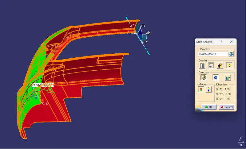
But here we will get a issue that the C surface will not follow the A surface that is because the sweep which we done is 90 degree to the a surface so it will be drafted on the core itself.
we will get the output in two colours one is green colour on top and other is red red red at the bottom. Which means the green color is 3 degree and the red color is less than zero degree and the red was not original before it was blue colour but for our reference I have I have changed it to the red color so that we can find it easily that it has a negative value.
after finishing the checking of drafting analysis we have to hide the drafting analysis and then our component is is ready to for manufacturing.
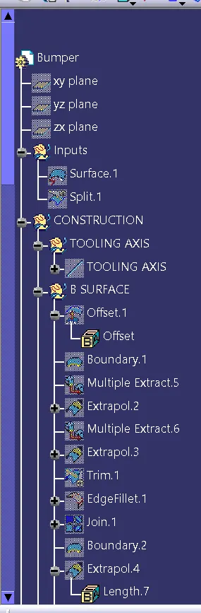
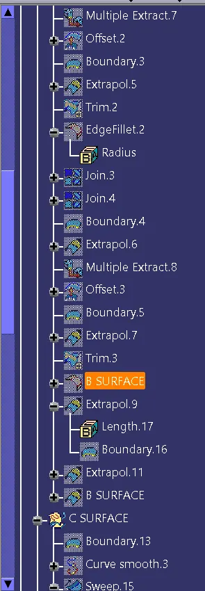
tree structure:
DIFFERENT VIEWS: