Week 9 - Project - A pillar Design with Master Section
A PILLAR DESIGN WITH MASTER SECTION
AIM: To create an a pillar design with the master section followed along with the class A surface provided and creating the B side features using CATIA V5
OBJECTIVE: The main objective of the challenge is to design an A pillar by following the master section provided to create a solid body and B-side features for a given class A surface, by considering all the design parameters.
MASTER SECTION:
Master Sections are the guides for design requirements which shapes the component after technical styling of Class A SurfacesThe body frame is mainly composed of floor longitudinal beams, upper side beams, door sill beams, and front cover, the rear beam, A-pillar, B-pillar, C-pillar and other load-bearing beam structures are composed.Master Sections are parameterized model of the vehicle body that outlines the guide for NEW PRODUCT DEVELOPMENT Team
In this Report A Pillar design is created with detailed procedure of Surface Development and B side features of dog house are covered
Procedure followed:
The following steps are included while designing the door handle with B side features
- Tooling axis creation
- Draft analysis of class A surface
- Class B surface generation
- class C surface generation
- Final trim
- Solid body generation
- Draft analysis of the solid body
- Dog house creation
- Rib base creation
- Top cutout creation
- Draft analysis of the B side features
Class A surface:
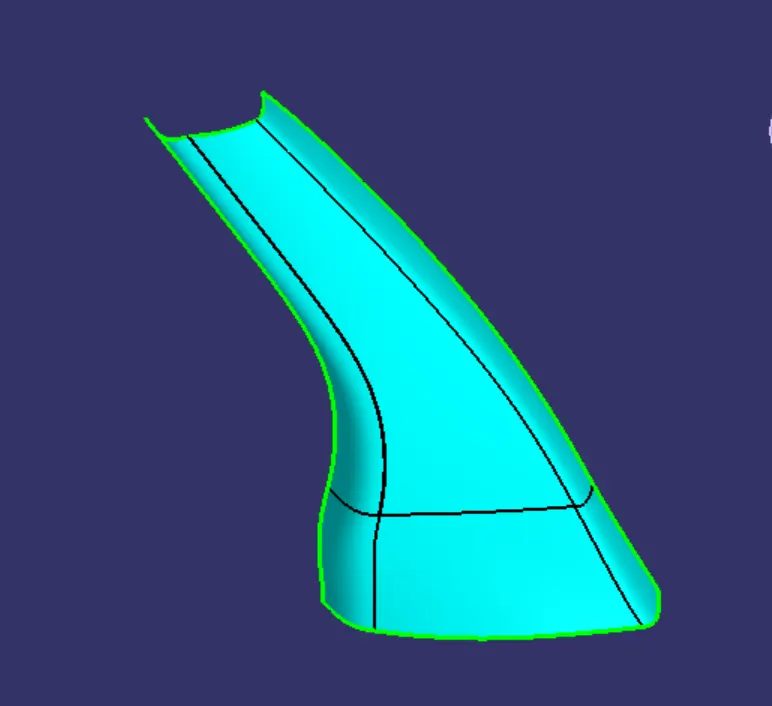
Class a surface is an asthetic surface with a polished surface which will be visible for the customers, and with the aid of the class A we could be able top geneate the class B and class C surfaces
For an A pillar design the class A provided is
Class B surface:
class B is an engineering surface where the B side features include the ribs, screw bosses , doghouses are located
Class C surface:
Class c is an intermediate surface between the class A and class B surfaces.It is generated by sweep feature either with reference surface or with the draft direction.If the generated C surface is parallel yo the tooling axis then we make the aid of the draft direction or else proceed with the reference surface
Commands deployed:
Surface commands:
- Extract
- Boundary
- Extrapolate
- Sweep
- Join
- Trim
- Intersect
- Multi section surface
- Surface extrude
- Multi extract
Part Workbench commands:
- solid surface
- Thicken
- Pad
- Draft
- Fillet
Tooling axis creation :
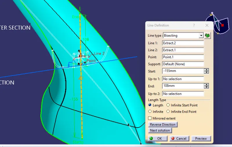
In the A pillat design the tooling axis is obtained by bisection method In this method we aid the use of the master section curves and create a point and form the two lines from the curves of the dog house in the master section and generate a line in between the two lines using the bisection method
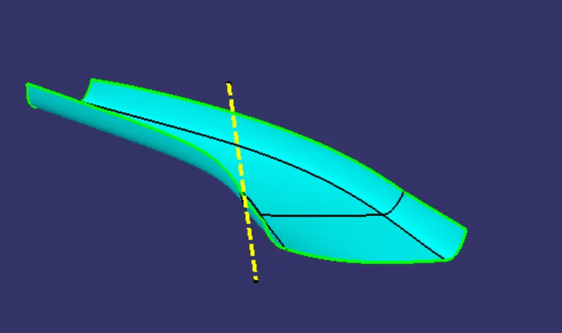
After creating the tooling axis then perform the darft analysis for the class A surface whether my tooling axis positioned in the right location so thet it can able to clear the draft analysis
DRAFT ANALYSIS ON THE CLASS A SURFACE:
Once the tooling axis is created perform the draft analysis for the class A surface providing the draft angle of 3 degrees
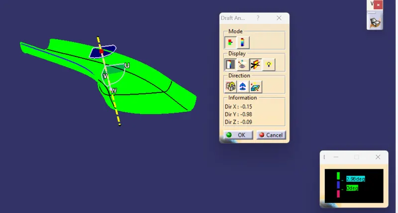
All most all the surfaces of the class a surface can be able to claet the draft along the tooling axis irrespective of one single corner surafce so the class A surface need to modified at that location because it has a draft angle of ranging from 2.7 to 2.8 degrees
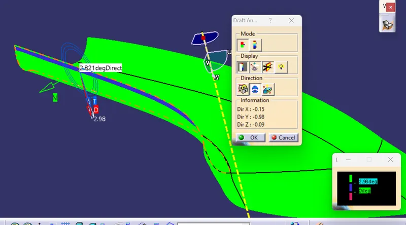
So we can make a note about the surface which has a lower draft and we can move forward by conforming thet the position of the tooling axis is accurate
CLASS B SURFACE CREATION:
For the class B surface offset the class A surface to a value of 2.5 mm beneath the class a surface
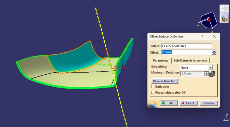
So the formed B surface be like
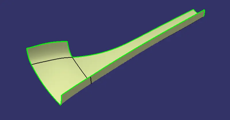
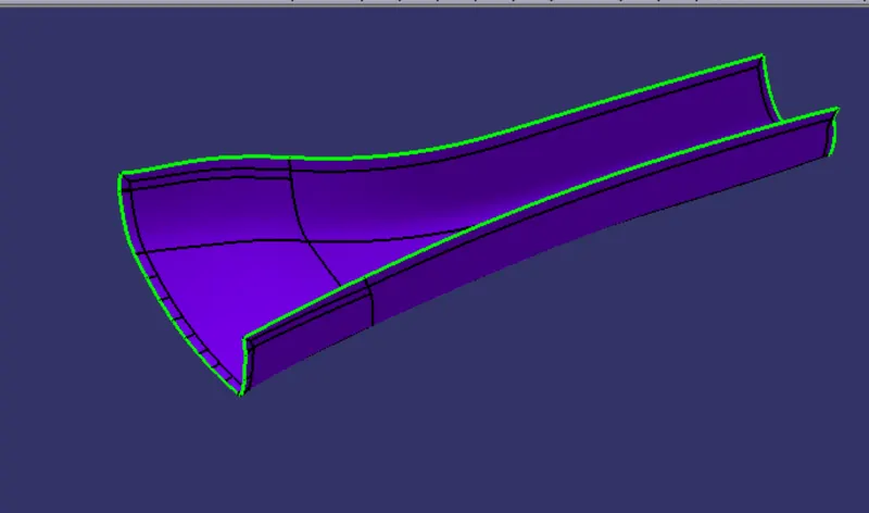
So we need to work on one single patch to create a final B surface with extrapolated on all edges as it will need to form the trim operation with the class C surface
CLASS C SURFACE CREATION:
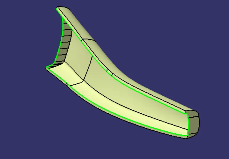
With the use of the class A surface we can create the class C surface with sweep command either by using along the reference surface or along the draft direction provideding angle of 90 degrees or 3 degrees of angle in case of sweep along the draft directionIf the class c surface is a parallel with the tooling axis direction then we need to use the sweep along the draft direction of 3 degrees so we need to create the sweep one after the other surafce rather than of generating the class c in asingle go as it might create some issues .
In this challenge the class a surface is not designed properly so I need to modify the class a surfa e to create a proper class c surface

so my final class c surface joine with class A surface is
FINAL TRIM:
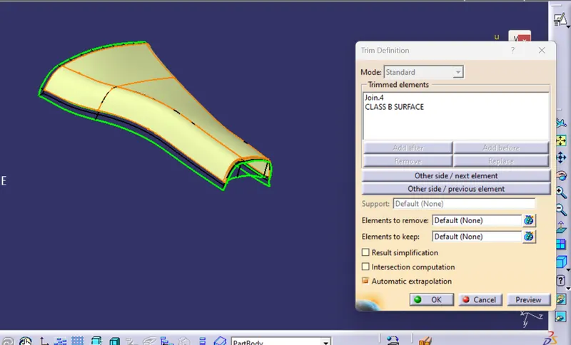
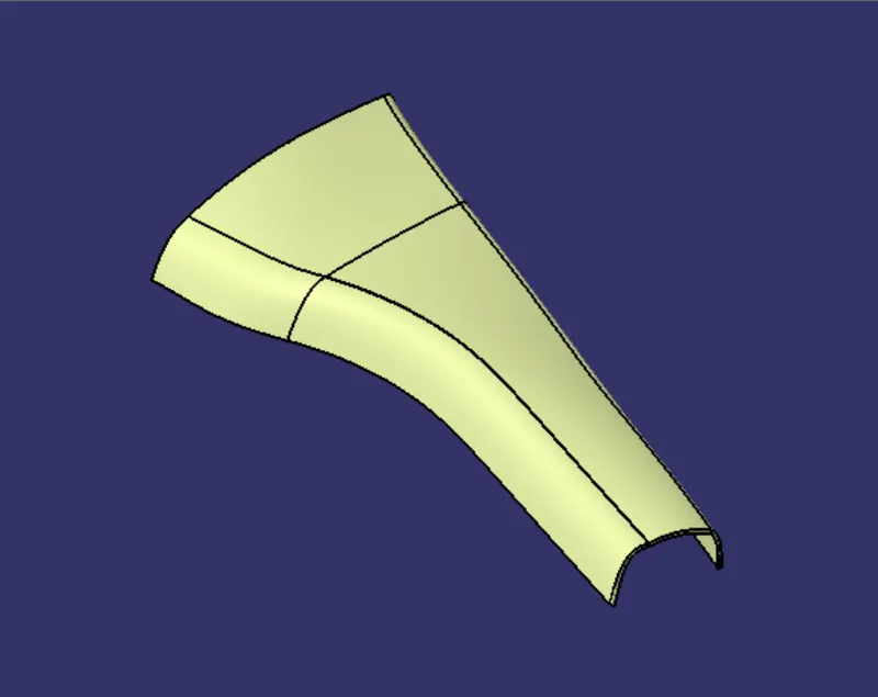
Now trim the class B with the Class C and A join the final surface obtained is
SOLID BODY GENERATION:
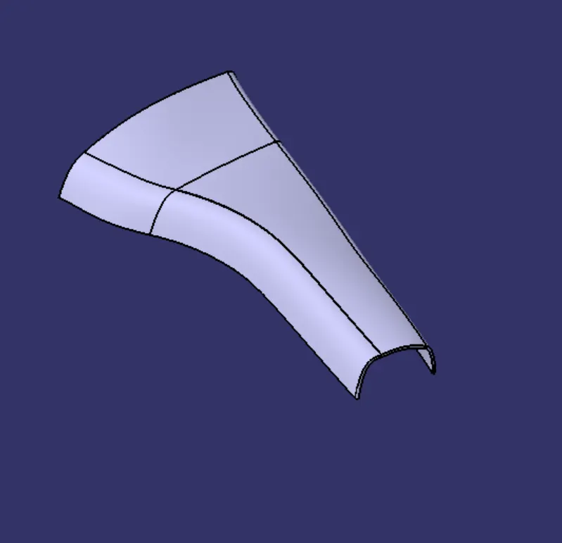
Now navigate to the part workbench and use the solid surface feature to create a solid body
DRAFT ANALYSIS ON THE SOLID BODY :
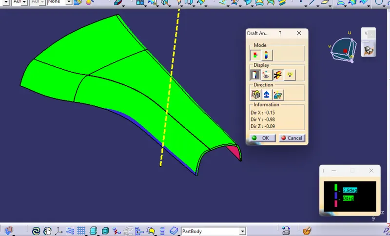
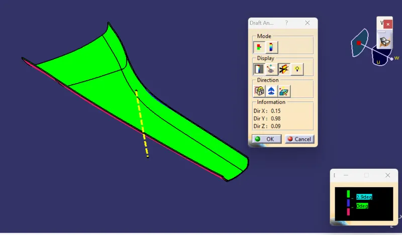
The draft analysis is done on solid part is to measure whether the all surface created clear the min draft angle of 3 deg, in this case some areas of the solid body is not clearing the min draft angle of 3 deg so these surface draft problems are created if the class surfcae is not designed properly and it need to be modified
DOG HOUSE CREATION:
Once the solid body creation is completed along with the proper draft analysis we can move forward for the creation of the class B side features
- For the dog house creation I creat a new axis system and follow the design measurements mentioned in the sketch provided for the dog house creation
- For this I draw o rectangle and extrude it and create a solid body and apply the skhell to a thichness of 2.5 mm inside
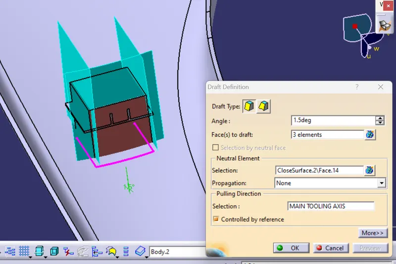
- Apply the draft on the outer side of the dog house with an angle of 1.5 degrees by taking the pulling direction as the main tooling axis
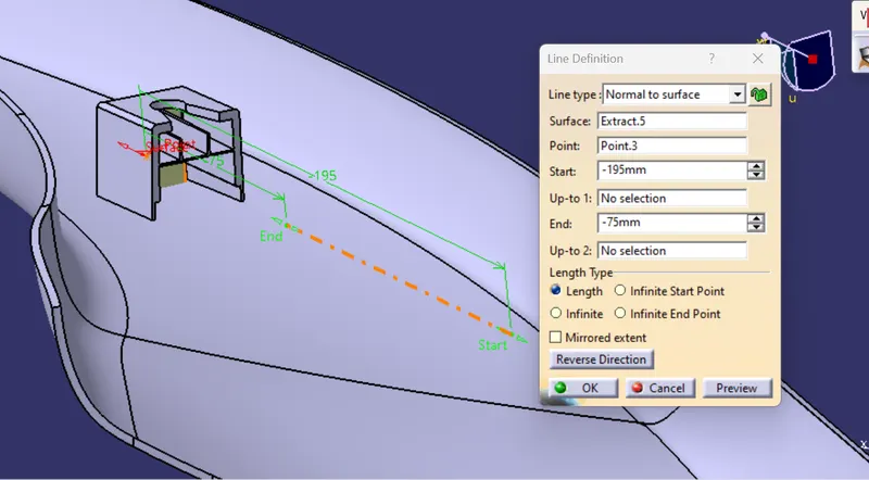
- Now to apply the draft on the inner side of the tooling axis we need to create a side tooling axis by extractinf the surfcae of the dog house and generating the line normal to the surface
- Now apply the draft on the inner side of the dog house with a value of the 0.5 gedrees by taking pulling direction as the side tooling axis
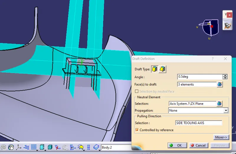
- Now create a coring of having 1 mm thick from the ouside walls and having a height of 3 to upto 6 mm and use the split command to make a proper cutout
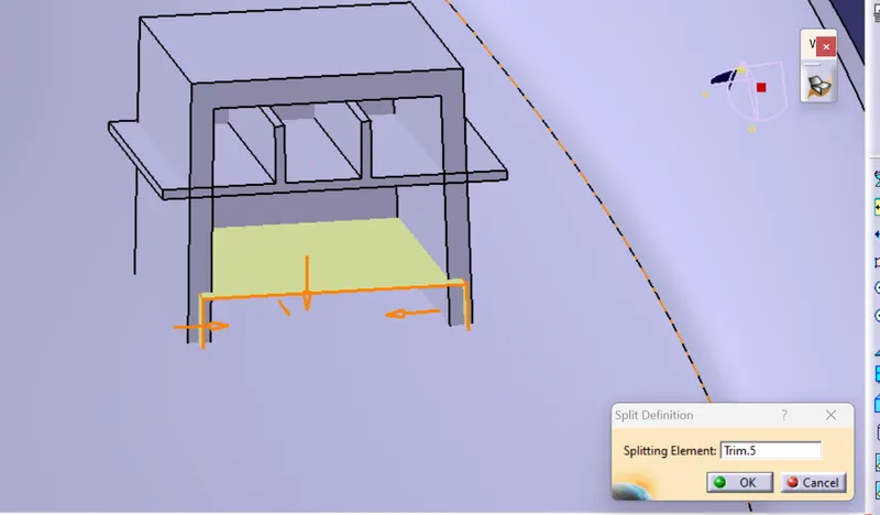
- Now apply the 0.5 degrees draft on the inner side of the coring
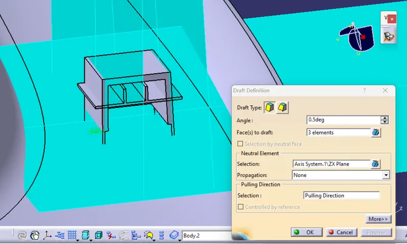
- Now create the rib base by taking the projection from the master section Taking taking the line and extrude the line and apply the thicken feature of 1 mm to sorm the solid body continue for the two ribs on the base and apply the boolan operation of union trim with the dog house
Now apply the draft analysis on the ribs base of 0.5 degrees by using pulling direction as the side tooling axis
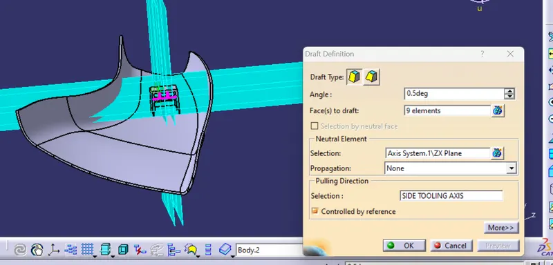
- Now create the sketch for the cutout on the top of the dog house
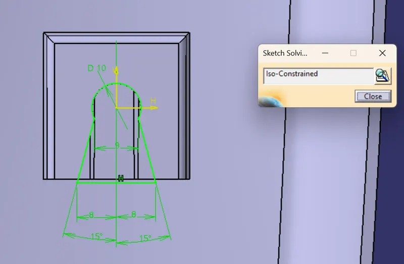
- Now extrude the surface and use the split option to make the proper cutout.
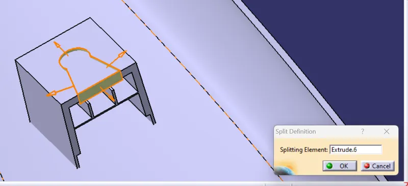
- Now apply the fillets on the inner and the outer side of the dog house
DRAFT ANALYSIS ON THE FINAL COMPONENT:
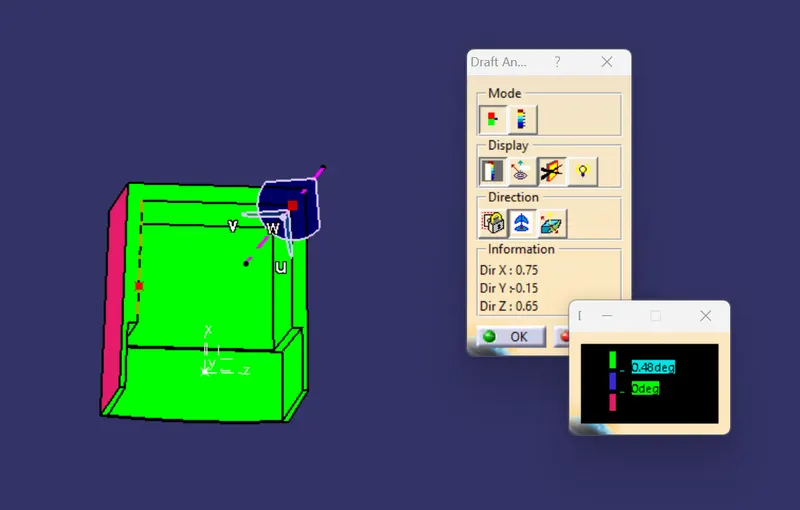
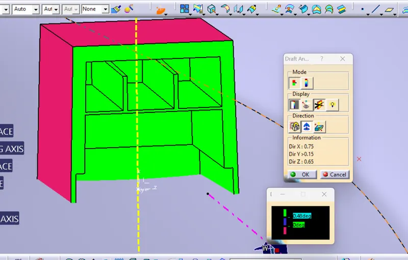
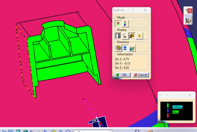
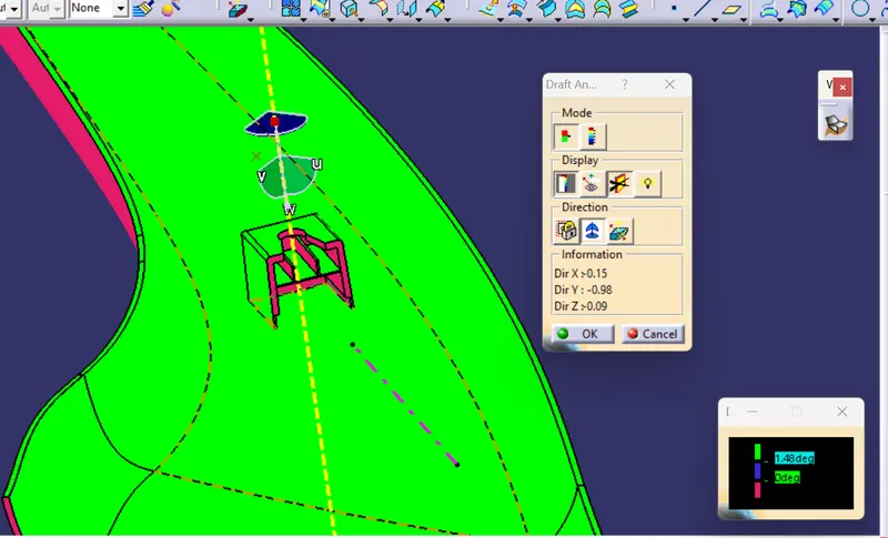
Now operform the draft analysis on the B side featuresc with an angle of 1.5 degrees on the outer sides of the dog house and 0.5 degres on the surfaces inside the dog house
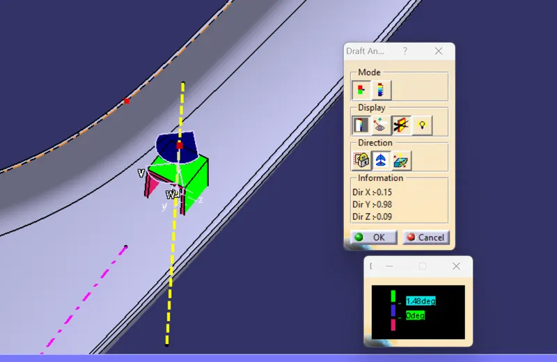
and 0.5 degres on the surfaces inside the dog house
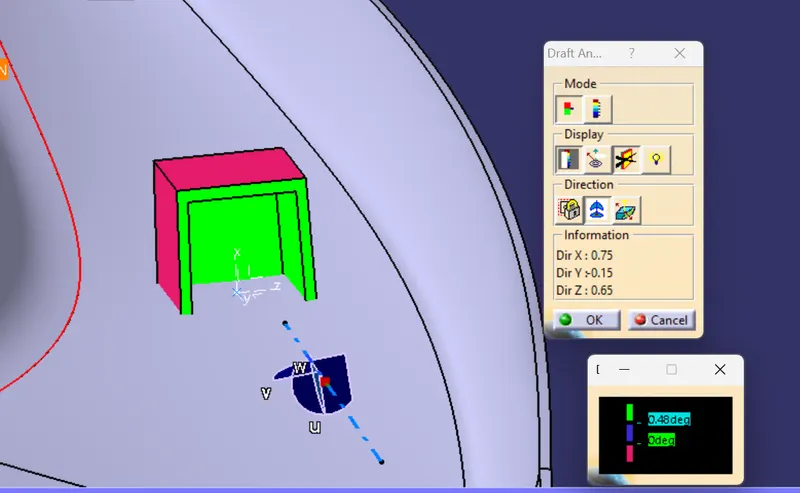
And the draft angle of 0.5 degrees on the coring and the rib base
CONCLUSION:
Hence an A pillar design is completed with the help of the inputs the class A surface and the master section for the B side features and performing the draft analyis for teh solid body with a draft angle of 3 gegrees and for the B side features that the dog house with an angle of 1.5 along the outer sides and 0.5 degree s in the inside includes the coring and the rib and the base for the ribs and the component is submitteed along with the report
VIEWS:
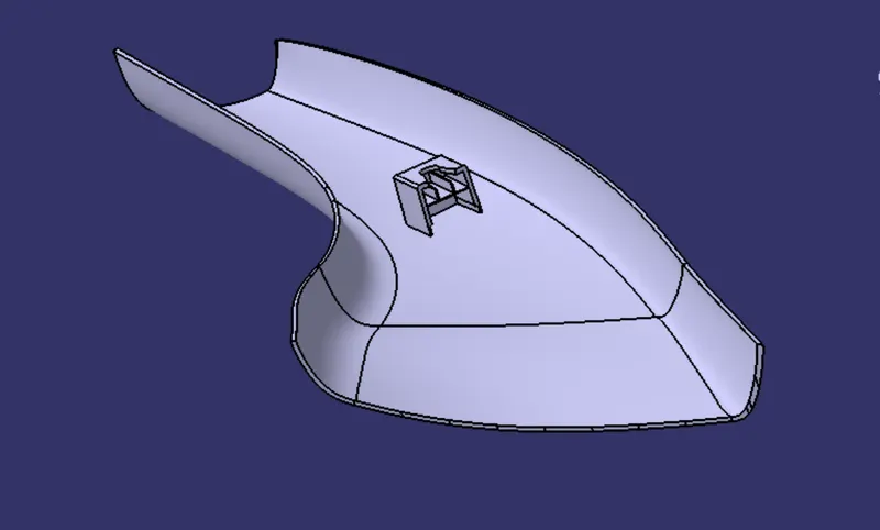
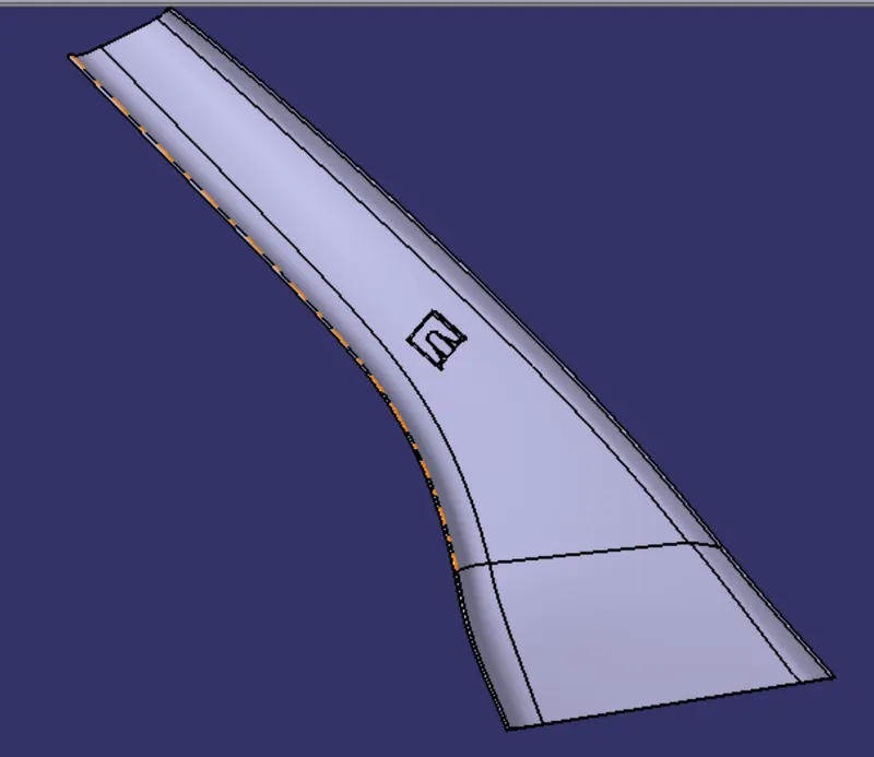
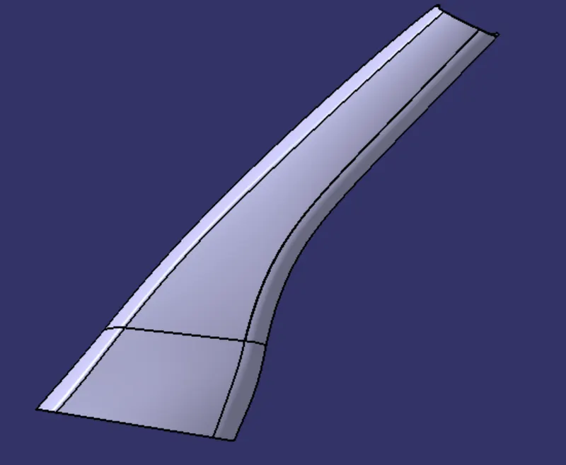
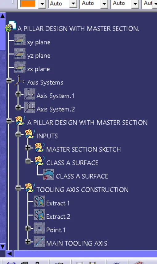
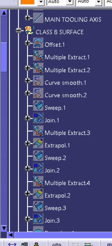
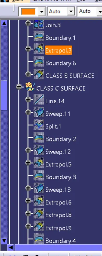
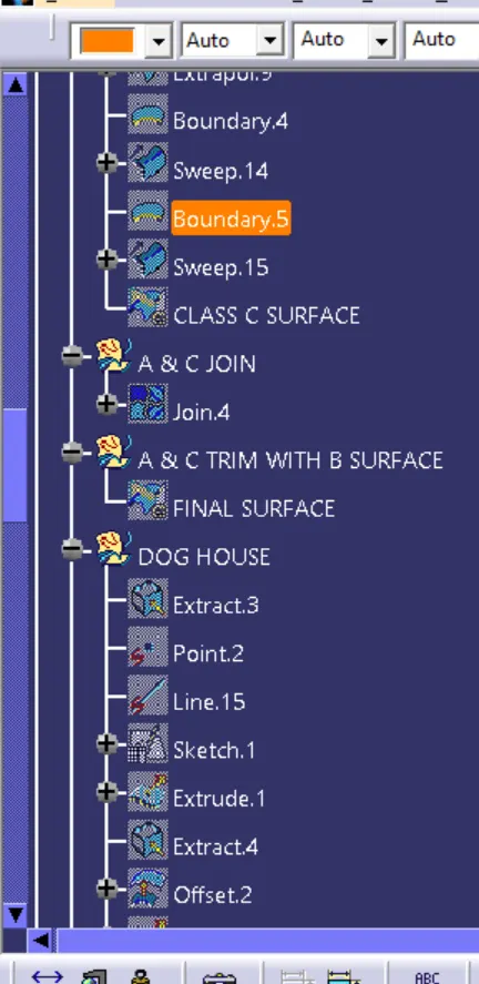
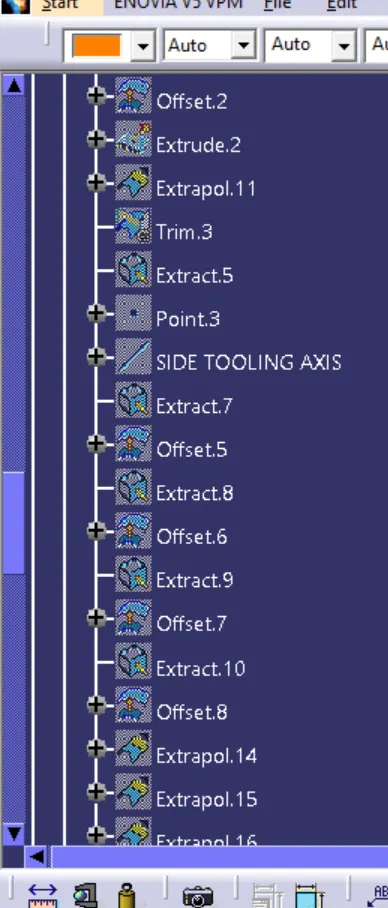
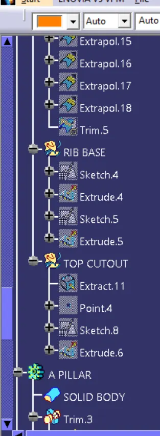
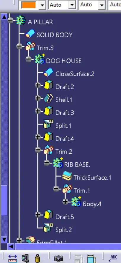
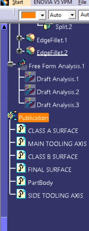
TREE STRUCTURE:
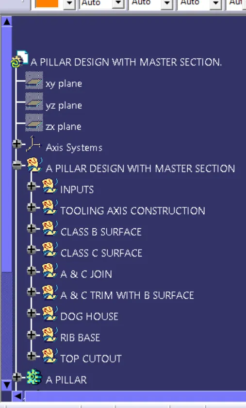
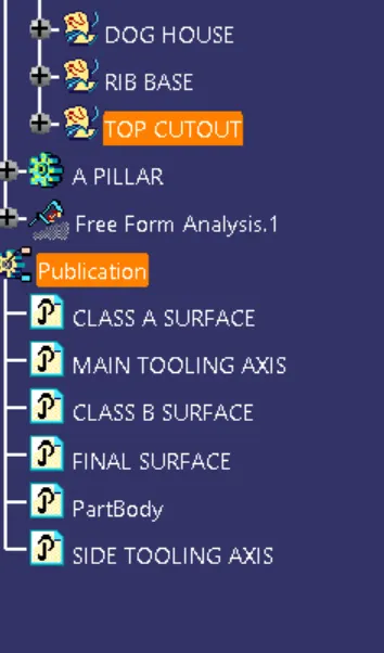
ENLARGED TREE STRUCTURE