Week 9 - Project - A pillar Design with Master Section
A PILLAR DESIGN WITH MASTER SECTION
Generally, the part component that we design must be manufacturable or toolable. As most interior and some exterior parts of automotives are made by plastics. And approximately 80% of them are manufactured by Injection molding. It have two halves- Core half, Cavity half, In which one is movable and the other one is fixed. Tooling axis direction is the direction in which Core half and Cavity half opens. All faces of the part component must clear the main tooling axis in order to be manufacturable, and there are exception in which sidecores and lifters are used additionally if holes or slots are present in the part component.
There are three ways to find the tooling axis direction-
1. X, Y, Z axis method
2. Normal to surface method
3. Bisecting method
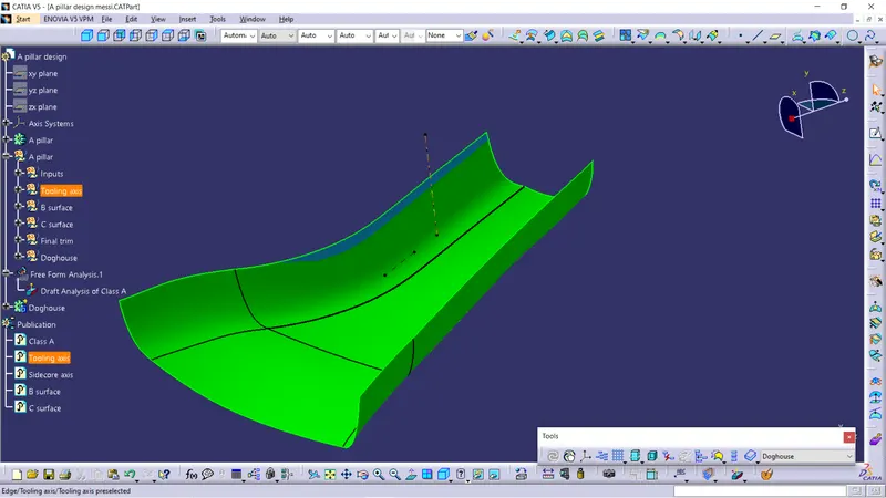
I've used Bisecting method in order to find the tooling axis direction of A pillar
Tooling axis direction of A pillar-
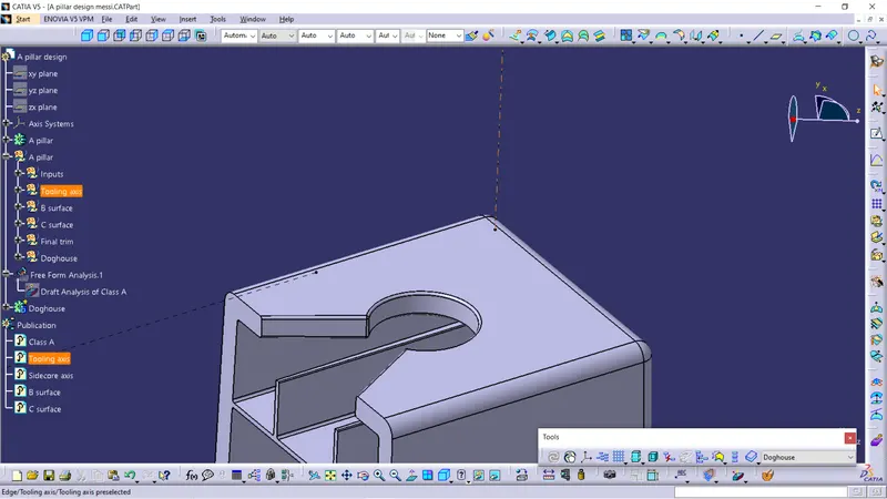
Sidecore axis of A pillar-
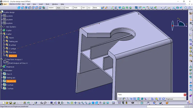
Doghouse: It is the engineering feature that will be present on the B surface of the part component
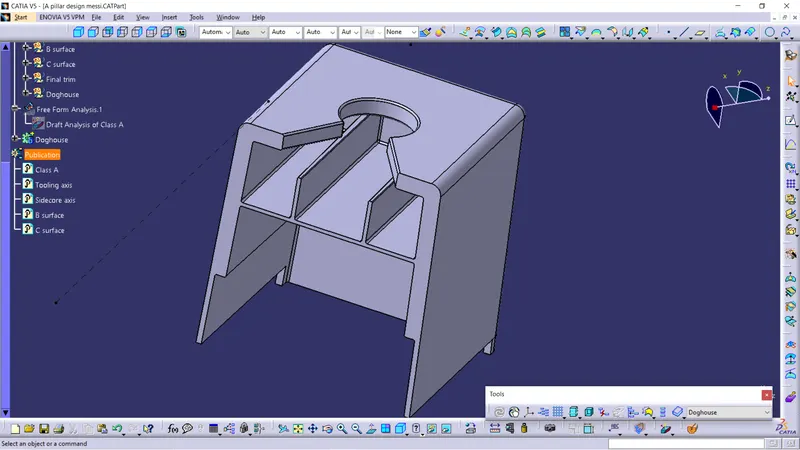
Applications: To avoid sink marks, To avoid length issues between the components, To position other engineering features that must be perpendicular to the part component.
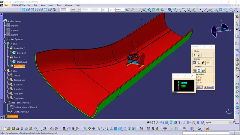
Draft analysis-
It is the technique that is used to analyse whether the part component that is designed in the catia part workbench can be manufacturable based on the draft condition applied.
Nominal draft value of Part component: 3deg
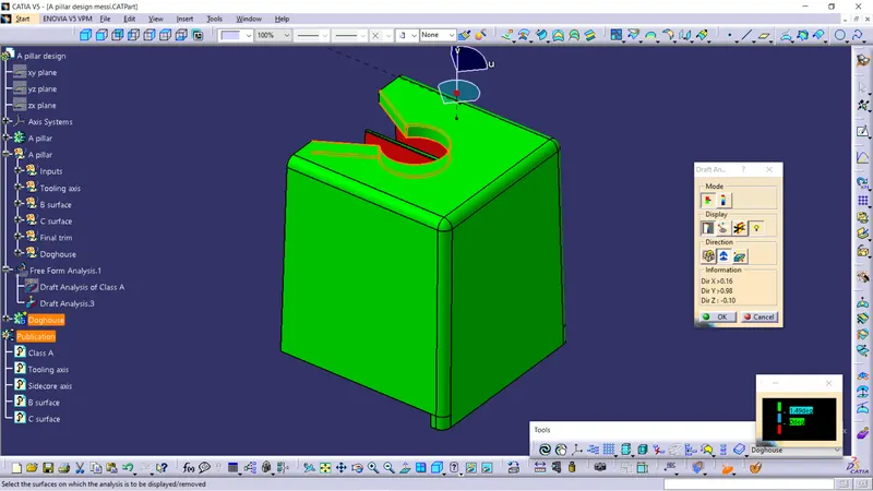
Draft of doghouse's outer surface: 1.5deg
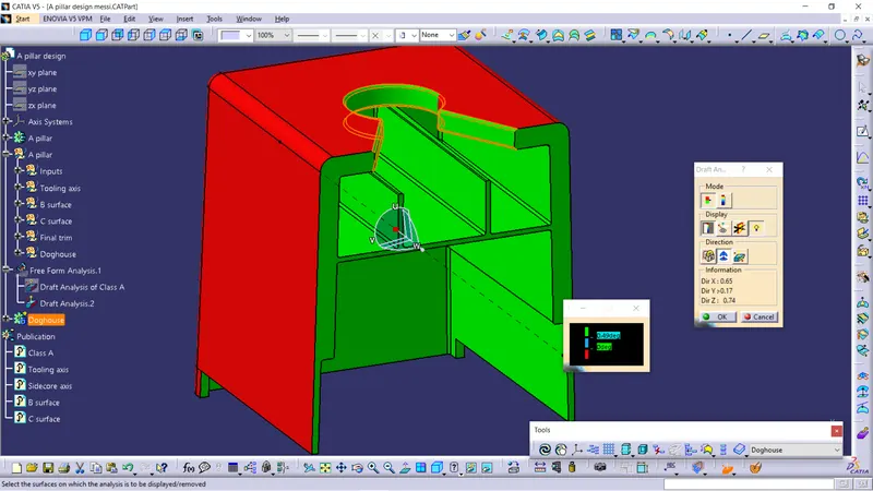
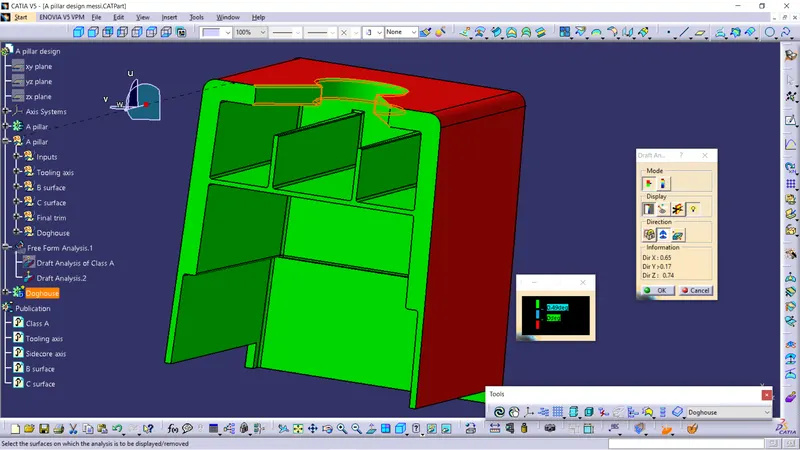
Draft of doghouse's inner surface: 0.5deg
Draft analysis of Class A surface-
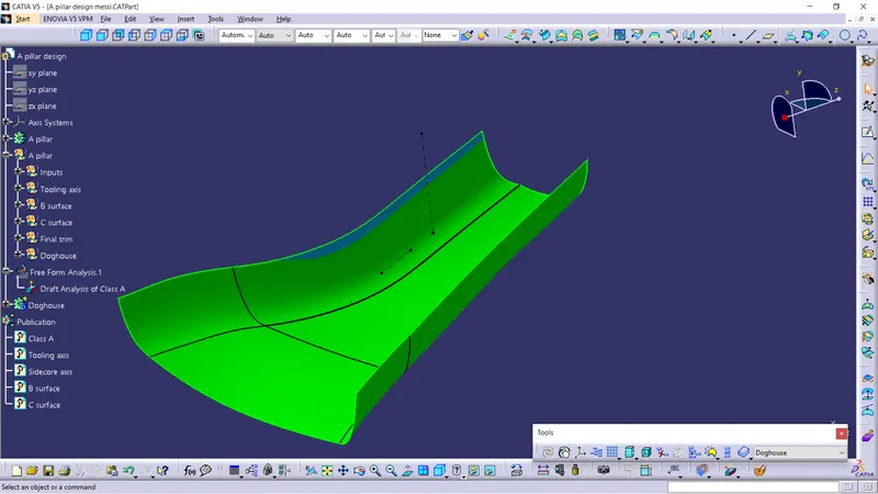
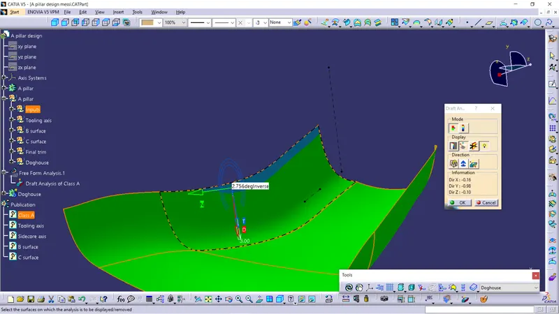
All the areas of the class A surface have a minimum draft of 3deg except the area that is mentioned in the above image. And this is due to the issue in the input class A surface.
Draft analysis of B surface-
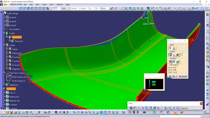
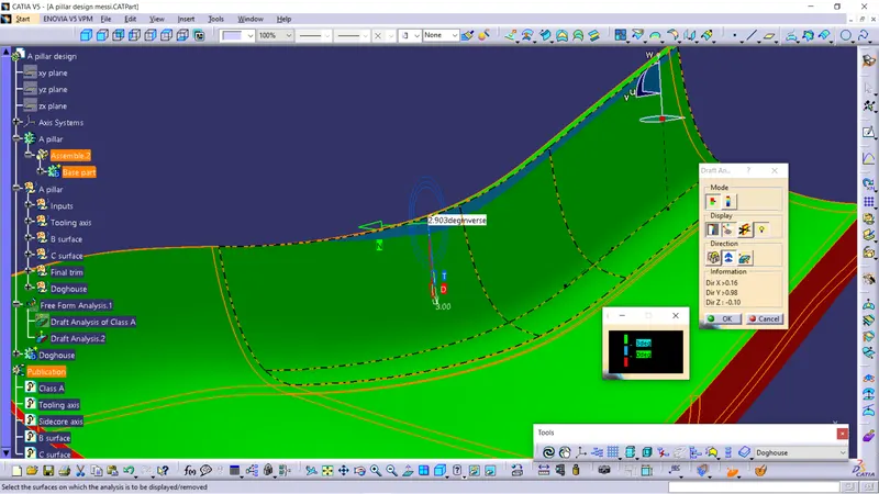
All the areas of the B surface have a minimum draft of 3deg except the area that is mentioned in the above image. And this is due to the issue in the input class A surface.
Issue in the draft analysis of C surface-
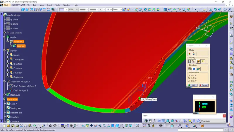
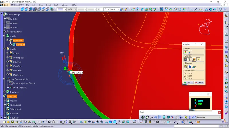
There is a red color code in the draft analysis of C surface and this is due to the issue in the input class A surface.
It have approximately -14deg which is impossible to be cleared by draft analysis
Draft analysis of Doghouse ( Outer surface )-
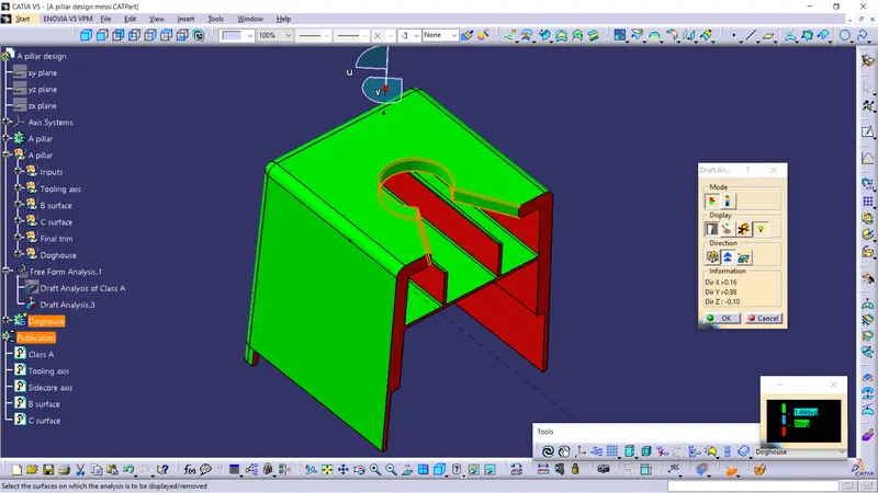
Draft analysis of Doghouse ( Inner surface )-
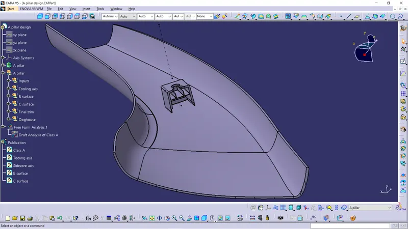
Final part component-
Draft analysis of final part component-