Week 8 - Challenge 4 - Bumper
BUMPER DESIGN
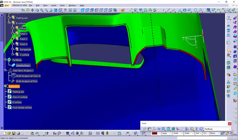
NOTE- There is a red color patch in the right view of draft analysis of part component. This is because the wall surface is in vertical axis direction, because that is parallel with the tooling axis So it can't be done with sweep by draft direction method. So I've done by sweep with reference surface method. And I've consulted with Mrs. Nivetha Vijaya kumar regarding the issue.
Generally, the part that we design must be toolable or manufacturable. In automotives, some exterior and most interior parts of automotives are made of plastics. In that 80% of the plastics are manufactured by Injection molding. Injection molding have two halves- Core half and Cavity half. In which Core half is movable and Cavity half is fixed. The part that we design must clear the main tooling axis direction, there are exception in which Sidecores are used if part contains holes or slots in it that cannot be cleared by main tooling axis. The tooling axis direction is the direction in which core and cavity opens. Each face of the part component must clear the tooling axis direction in order to be toolable or manufacturable.
There are three methods to find the tooling axis of part component-
1. X, Y, Z axis method
2. Normal to surface method
3. Bisecting method
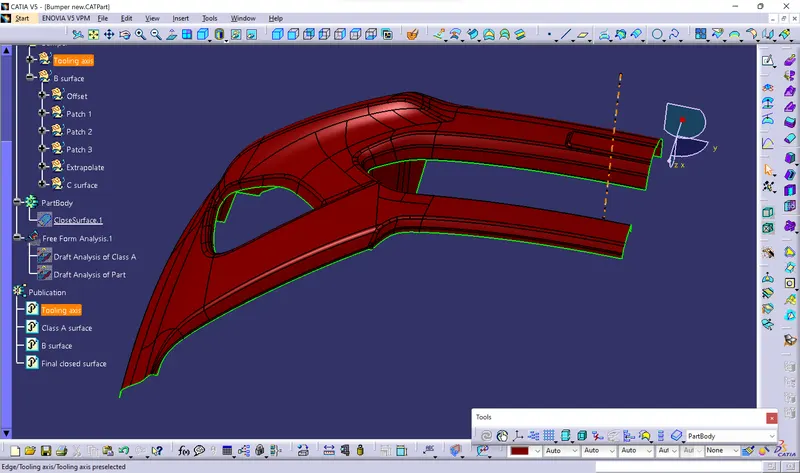
For finding the tooling axis direction of Bumper, I've used X, Y, Z axis method.
Tooling axis direction of Bumper-
It is in the direction of X axis
Draft analysis-
The part component that we design must have minimum draft in all faces of the component. This minimizes the collision of the part with mold of injection molding machine to avoid damages.
Nominal draft value is 3 degree
The draft value for Instrumental panel is 7 degree
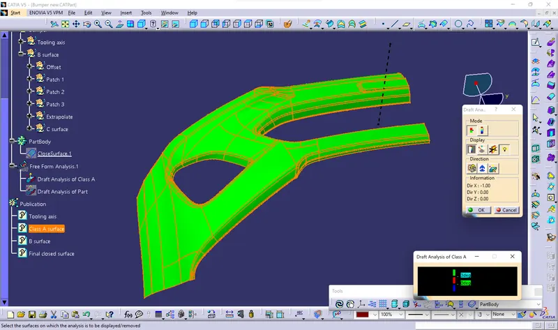
It is a technique that is used to analyze whether our part model created in Catia's part workbench is manufacturable based on the draft direction applied.
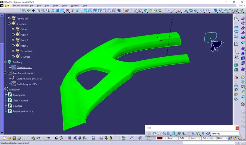
Draft analysis of Class A surface:
Draft analysis of Part component:
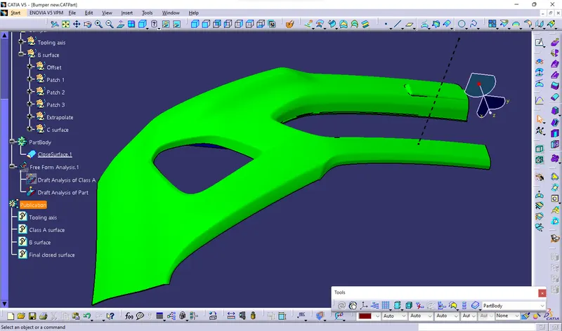
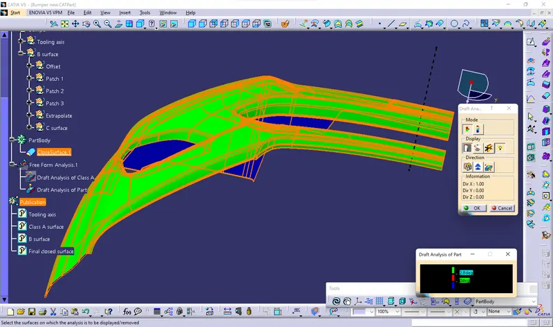
Solid model with the proper color code of the draft angle in different orientations-
Isometric view
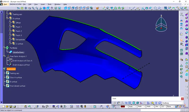
Front view
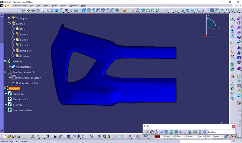
Back view
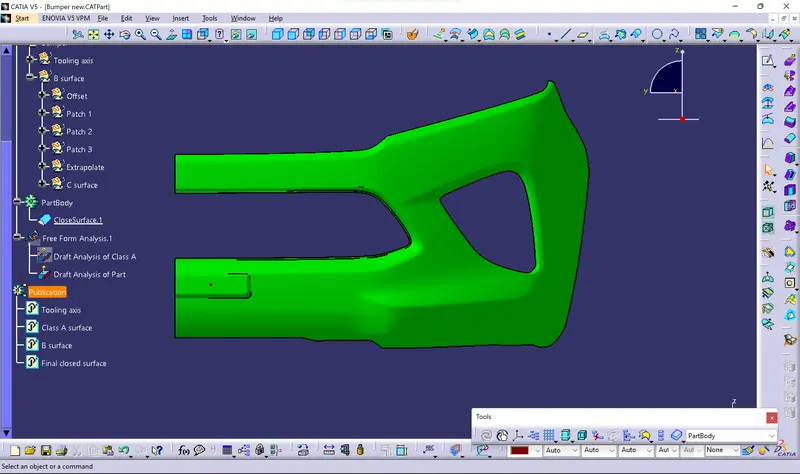
Side view
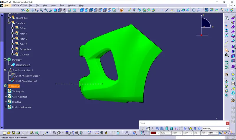
Top view
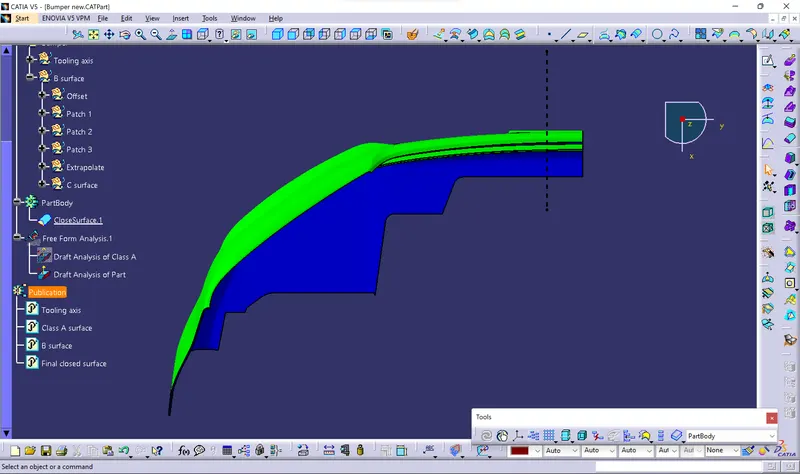
Bottom view
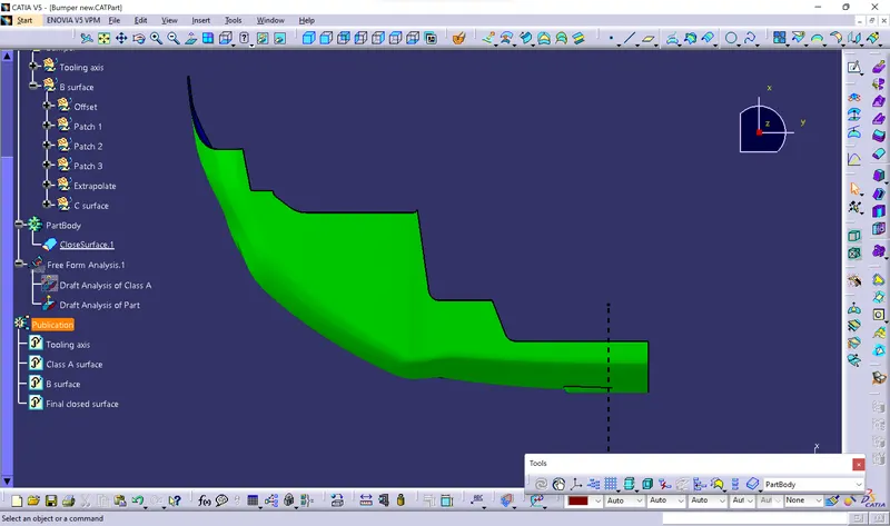
NOTE- There is a red color patch in the right view of draft analysis of part component. This is because the wall surface is in vertical axis direction, because that is parallel with the tooling axis So it can't be done with sweep by draft direction method. So I've done by sweep with reference surface method. And I've consulted with Mrs. Nivetha Vijaya kumar regarding the issue.