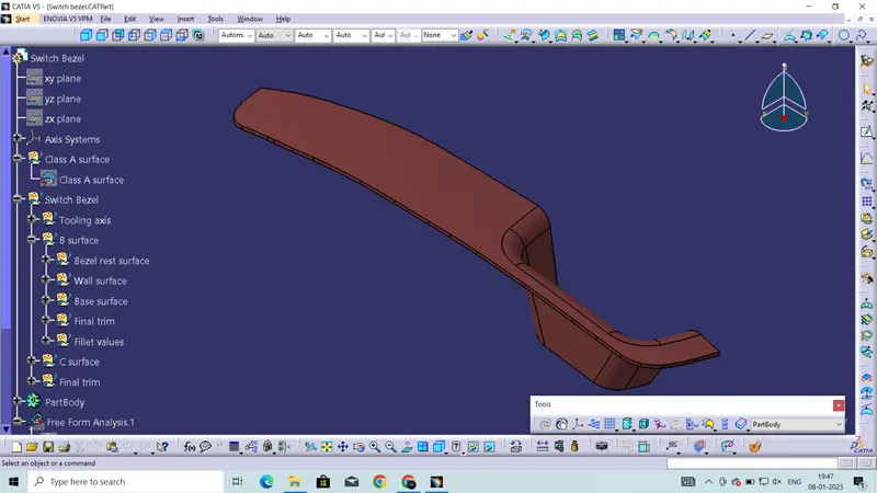
Week 8 - Challenge 2 - Switch Bezel Design
1. SWITCH BEZEL
Generally the part component that we design must be toolable and manufaturable. As we know that 80% of automotive plastic components are manufactured by Injection molding. Injection molding have two halves Cavity and Core, in which one is movable and the other one is fixed. The part component must clear the main tooling axs direction in order to manufacture, but there are other case in which Sidecores are used when the part have hole or slot in it. Each face must be cleared by tooling axis. The faces that is parallel and perpendicular to the tooling axis direction would be cleared with ease. The face that is in a angle( Acute or Obtuse ) with a tooling axis direction will be bisected in order to get the tooling axis.
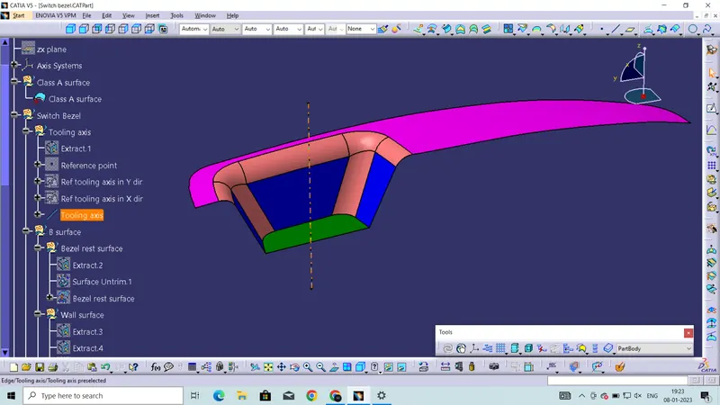
Tooling axis of Switch bezel-
The faces that makes particular angle other than parallel or perpendicular will be taken as a reference. The intersection will be made between the other two planes and the Class A surface. The bisecting line will be created by taking that face lines as reference. And the bisecting line will be considered as Tooling axis.
Draft analysis -
The draft analysis will be performed for both the Class A surface and the final part component. It allows the designer to easily analyze a part for proper draft angle.
3 degree is the norminal draft angle
Draft analysis of Class A surface
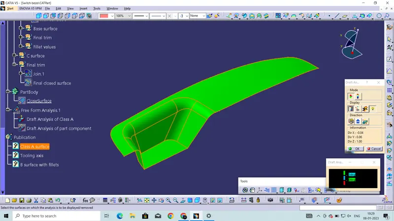
Full draft analysis mode of Class A surface
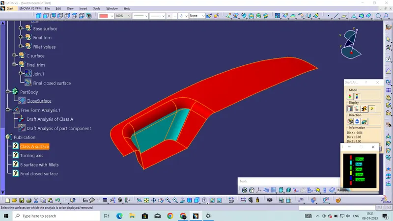
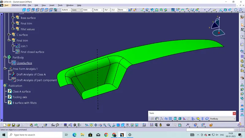
Draft analysis of final part component-
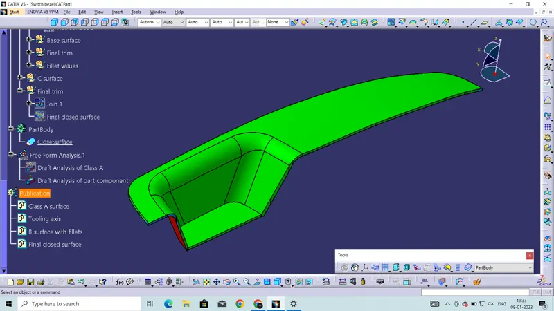
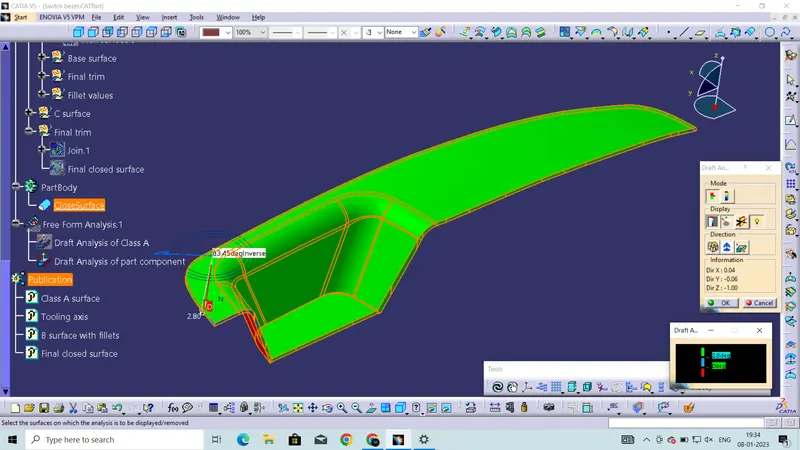
Full draft analysis of final part component
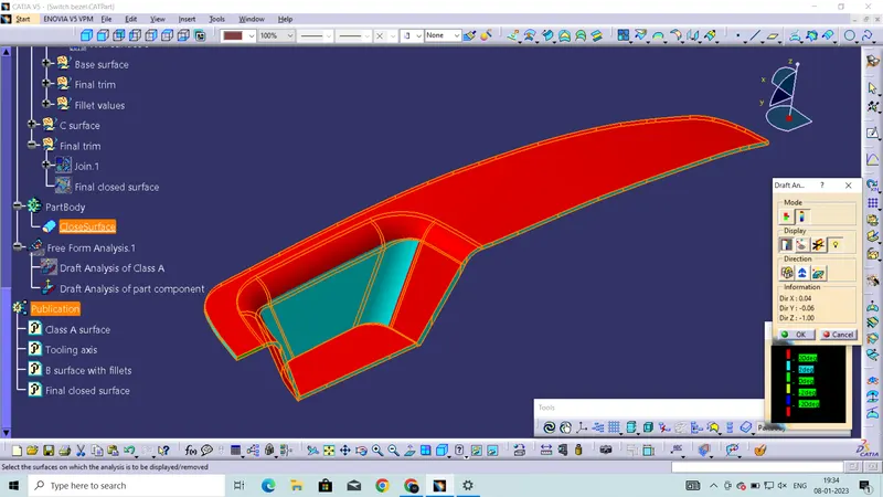
Solid model with the proper color code of the draft angle in different orientations-
Isometric view
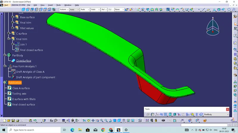
Front view
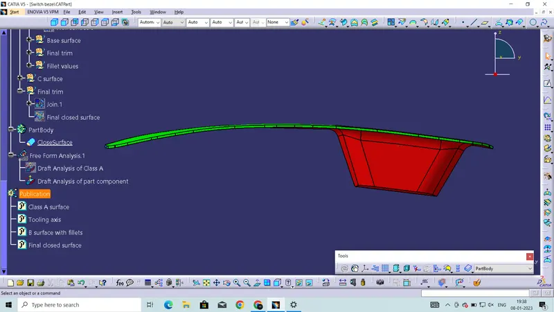
Back view
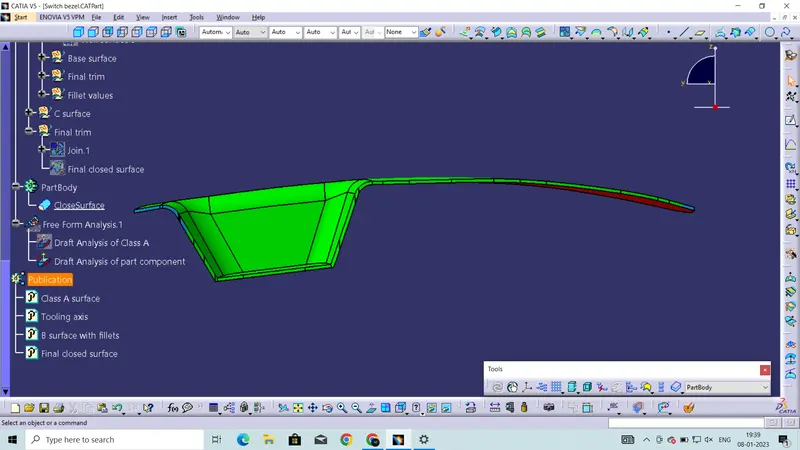
Side view
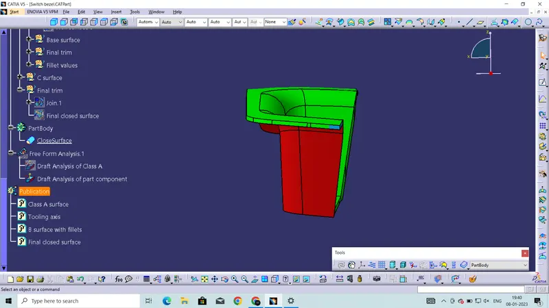
Top view
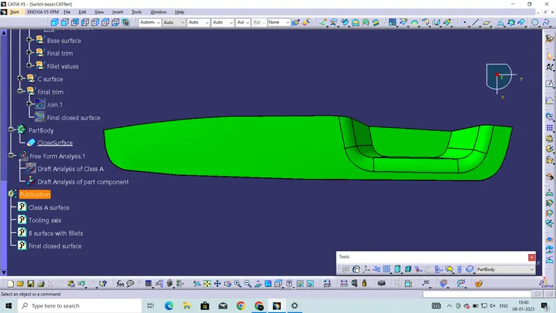
Bottom view
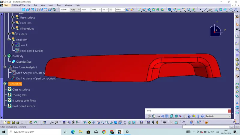
Solid model