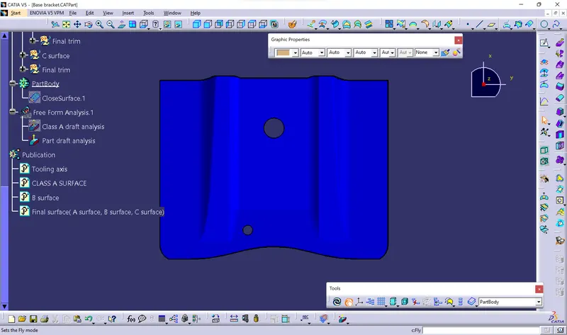
Week 8 - Challenge 1 - Base Bracket Design
1. BASE BRACKET DESIGN
Generally the part that we design must be eligible for toolable and manufacturing. Most of the automotive components are manufatured by Injection molding. Injection molding have two halves Cavity and Core. In which one is movable and the other one is fixed. The part that we manufacture must clear the main tooling axis, there are other case in which Sidecores are used additionally for the creation of holes and slots. But they would make the production costlier. We must design in a way to avoid sidecore without affecting its functionality.
If we have chosen the tooling axis, every face of the surface must clear the tooling axis direction. If a class A surface have large space of flat surface or holes in it, the normal to it will be the direction of the tooling axis. The dummy tooling axis must be created as a reference in the direction of mold opening. The face that is perpendicular to the tooling axis will be easy for manufacturing but the face with some angle with the tooling axis must be checked whether it will clear the tooling axis direction.
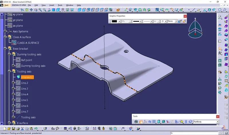
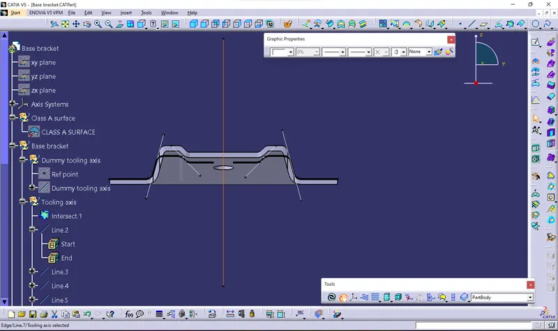
In the case of base bracket design, the Z axis is taken as the Tooling axis. The axis system is created in the reference point in which the tooling axis lies. The intersection is made between the class A surface and the other two planes in order to get the intersection sketch of face. The face sketch that is neither parallel nor perpendicular is extended for reference, the bisection of the extended lines would give the direction of tooling axis. The bisection will be taken in both the face sketch of the two planes.
Intersection of face sketch, between surface and yz plane:
Bisecting line:
Tooling axis:
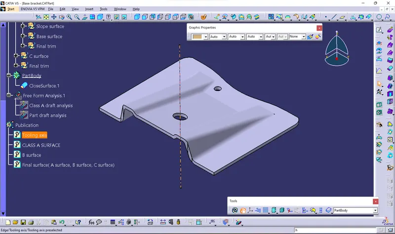
The tooling axis direction play a key role in the creation of the C surface.
DRAFT ANALYSIS-
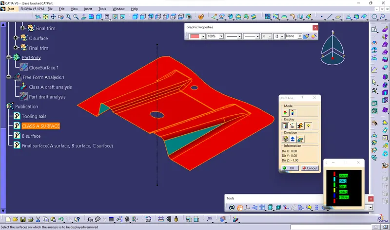
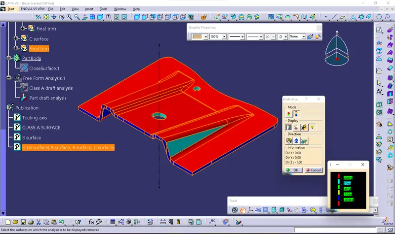
The draft analysis must be performed for the Class A surface and the final plastic component, it is used to analyze whether our part model is manufacturable based on the draft condition.
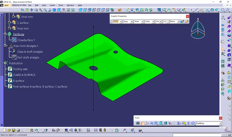
Draft analysis of class A surface
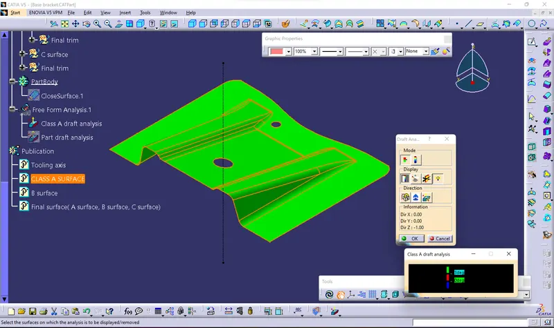
Draft analysis of class A in full analysis mode
Draft analysis of the final plastic component
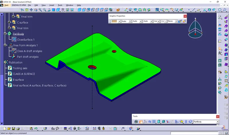
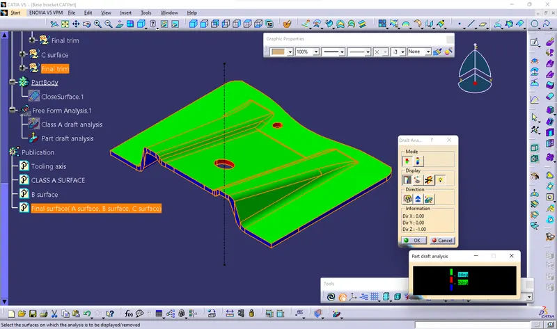
Draft analysis of part in full analysis mode
SCREENSHOTS OF THE SOLID MODEL WITH THE PROPER COLOR CODE OF THE DRAFT ANGLE IN VARIOUS ORIENTATIONS-
ISOMETRIC VIEW
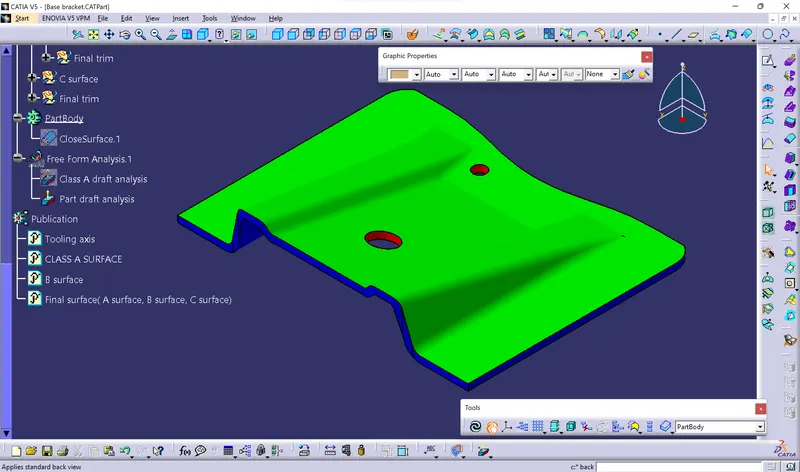
FRONT VIEW
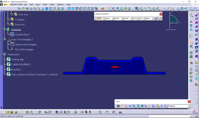
BACK VIEW
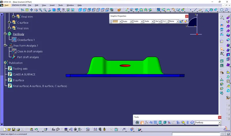
SIDE VIEW
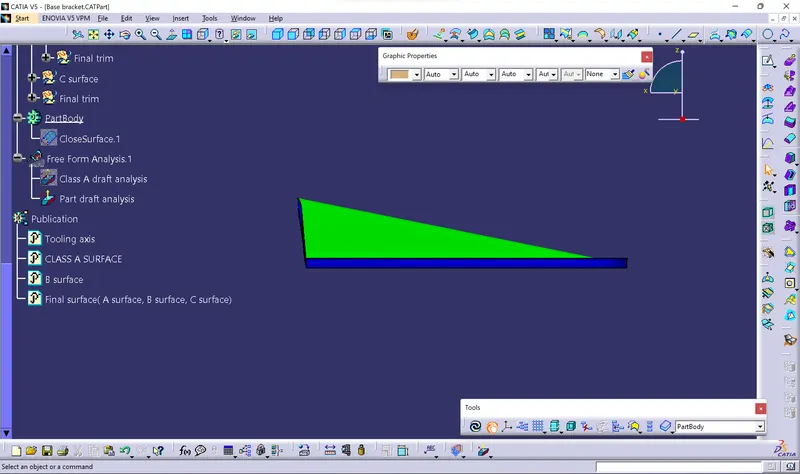
TOP VIEW
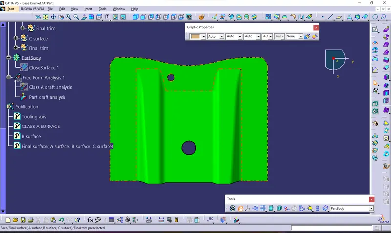
BOTTOM VIEW