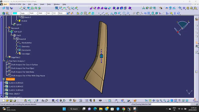
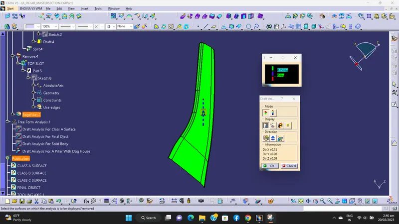
Week 9 - Project - A pillar Design with Master Section
PROJECT 2 - A PILLAR DESIGN WITH MASTER SECTION
DESIGN PROCEDURE -
1) Class A surface check.
2) Creating tooling axis.
3) Draft analysis on Class A surface.
4) Creation of Class B surface.
5) Creation of Class C surface.
6) Final trimmed surface.
7) Convert surface to solid.
8) Creation of Dog House with help of master section.
1) Class A surface check -
This surface is provided by styling team. This Class A surface is check by using boundary command, if there is irregularities then it is clear by using join command.
Then by using publication tool Class A surface is published.
2) Create tooling axis -
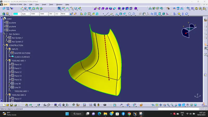
Tooling axis is a line of direction where core and cavity will open.
In bisecting tooling axis method, analyze the model manually or visually to see which direction is most suitable for tooling axis.
In this project of A-pillar design with master section, we create the bisecting tooling axis with the reference of master section.
In which, we create 4 points with the reference of cutsection of dog house. We also create one middle point.
After that we create two line which is pass through this 4 points respectively.
Then we create one line which is bisecting this two line and pass through the middle point. This is our main tooling axis.
Then published tooling axis by using publication tool.
BISECTING TOOLING AXIS -
3) Draft analysis for Class-A surface -
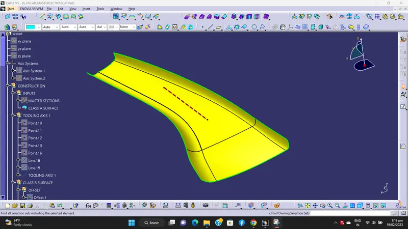
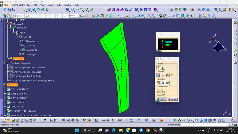
By changing the view mode to custom view, in the parameters – Material mode is selected. Then the feature of draft analysis is enabled.
Then the compass was activated and placed with the tooling axis by dragging the red pointer and then locked it.
Then, by selecting the quick analysis mode, the nominal value will be 3 degrees and checked for the components draft angle.
The green colour area shows that it satisfies the 3-degree draft angle.
If not satisfied then by using the running point tool the area is measured and then altered to get a successful draft for the created tooling direction.
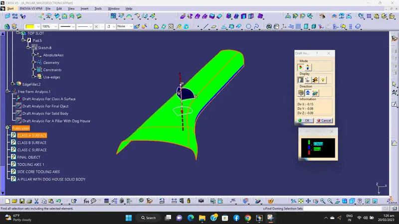
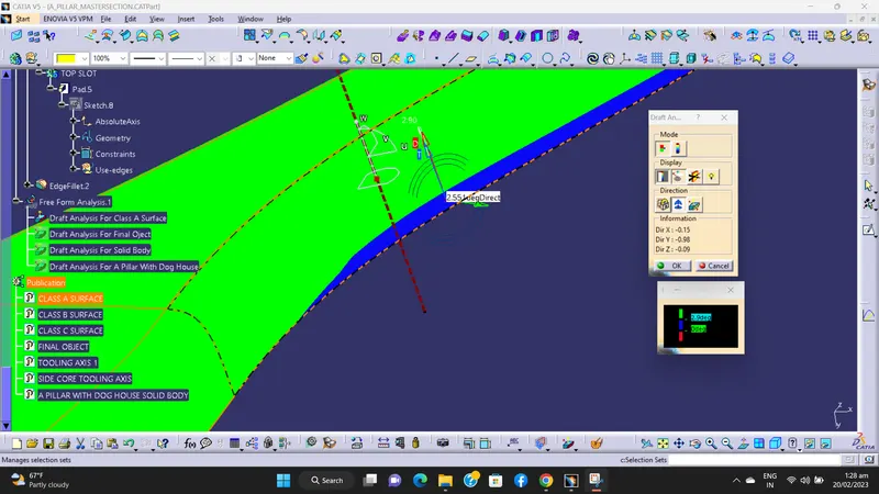
In above image, the blue colour show the Class-A surface is not cleare the draft analysis with 2.9deg.
There is the minimum 2.5 deg draft.
4) Creation of Class-B surface -
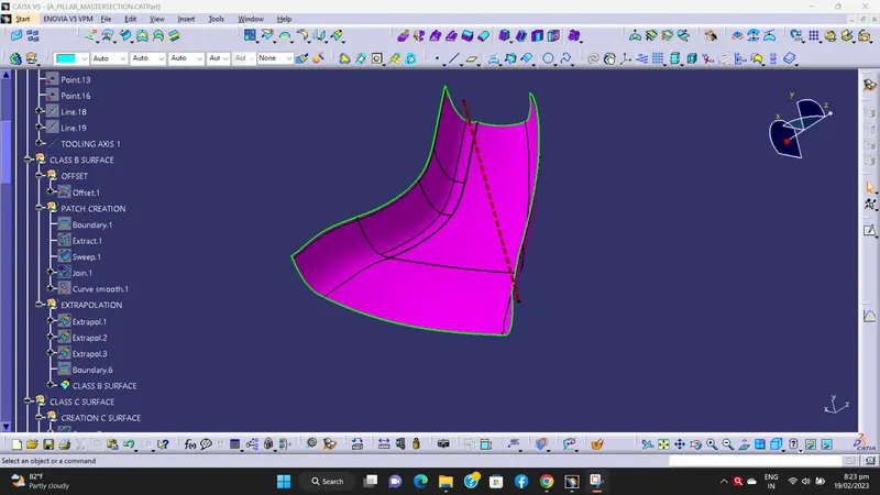
For creating the Class-B surface, we offset Class-A surface in downward direction by 2.5mm.
Then all the missing fillet patches or other surfaces are created by using multipale extract,extrapolate and trim command.
Finally, the required corners have been filleted by reducing the thickness value 2.5mm
Then published Class-B surface by using publication tool.
5) Creation of Class-C surface -
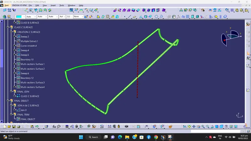
For the creation of Class-C surface, creating the boundary for Class-A surface.
Then by using the sweep command the surface was created by selecting respective boundary.
So get our Class-C surface.
After that we published Class-C surface by using publication tool.
6) Final trimmed surface -
Now the Class–A surface is join with the surface which created by using sweep command.
Now this join is trimmed with Class-B surfaces.
We got required final trimmed surface.
Then published final trimmed surface by using publication tool.
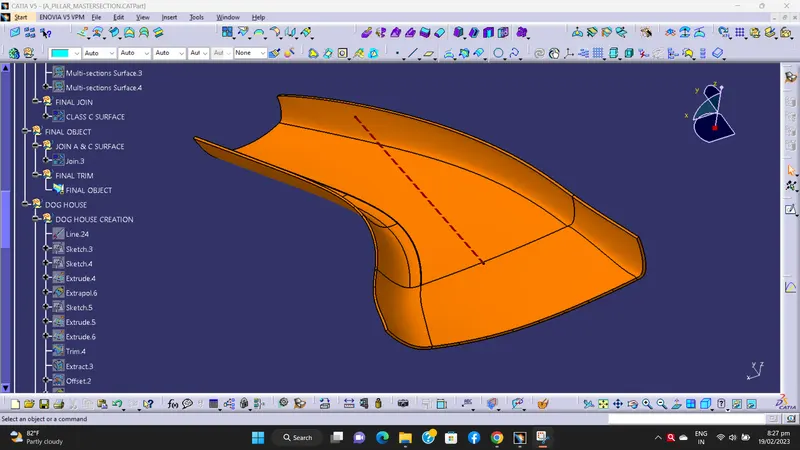
Draft Analysis For Final Object -
a) Class-A surface -
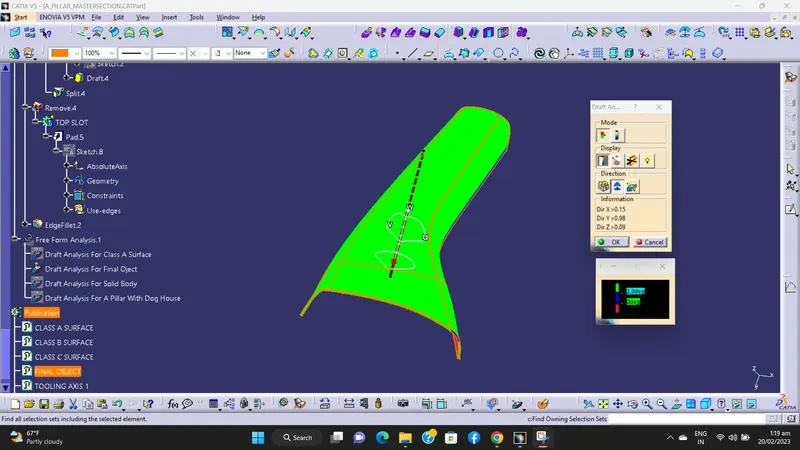
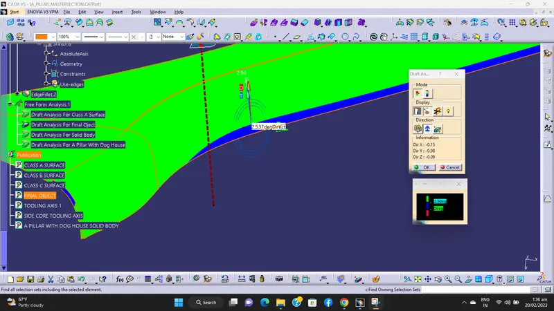
In above image, the blue colour show the Class-A surface is not cleare the draft analysis with 2.9deg.
There is the minimum 2.5 deg draft.
b) Class-B surface -
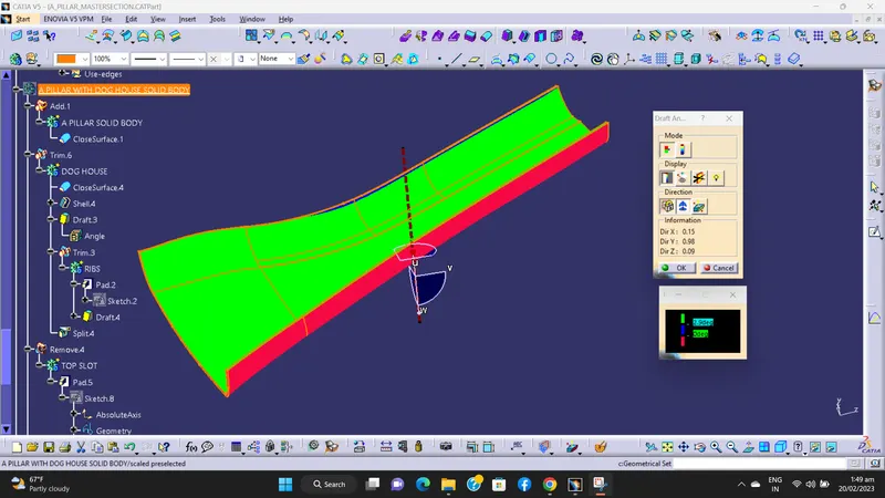
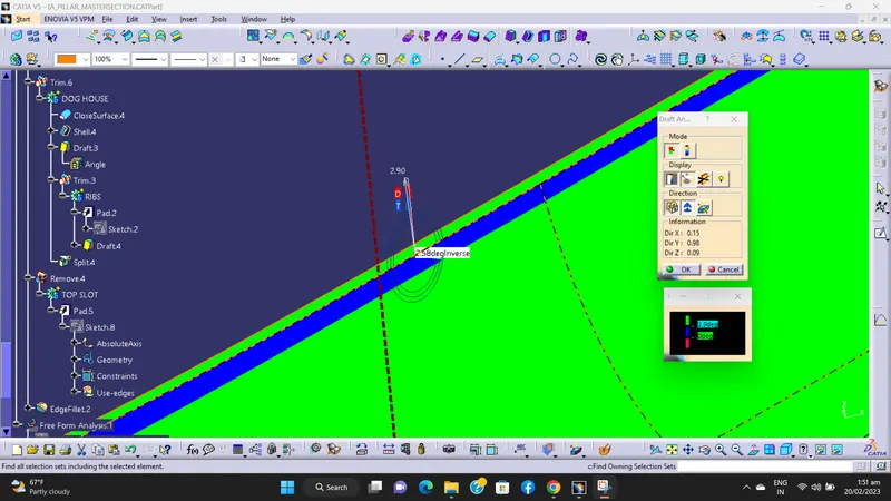
In above image, the blue colour show the Class-B surface is not cleare the draft analysis with 2.9deg.
There is the minimum 2.58 deg draft.
b) Class-C surface -
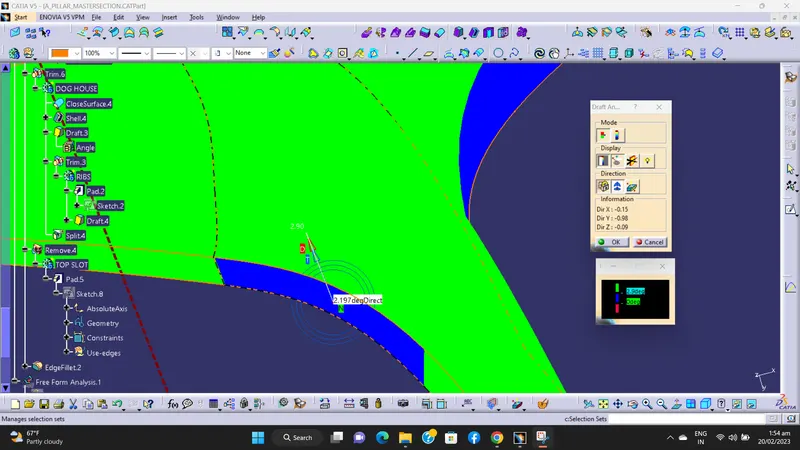
In above image, the blue colour show the Class-C surface is not cleare the draft analysis with 2.9deg.
There is the minimum 2.1 deg draft.
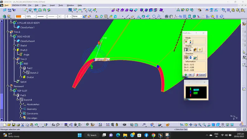
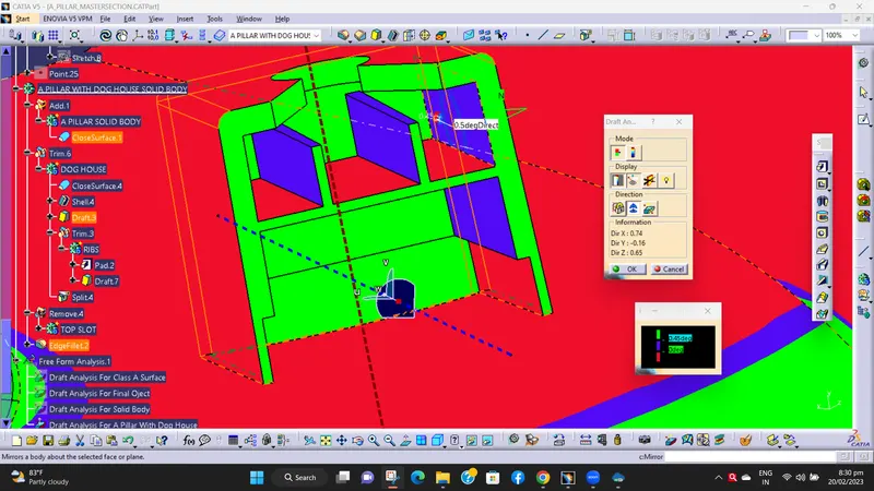
In above image, the blue colour show the Class-C surface is not cleare the draft analysis with 2.9deg.
There is the minimum 0.6deg draft.
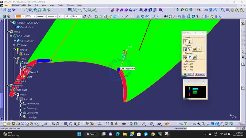
In above image, the blue colour show the Class-C surface is not cleare the draft analysis with 2.9deg.
There is the minimum 0.5deg draft.
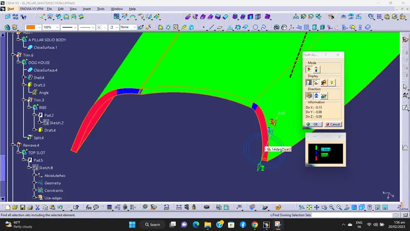
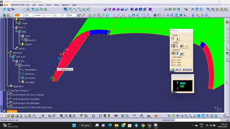
In above tow images, the red colour show the Class-C surface is not cleare the draft analysis with 2.9deg.
There is the less than 0deg draft.
7) Convert surface to solid -
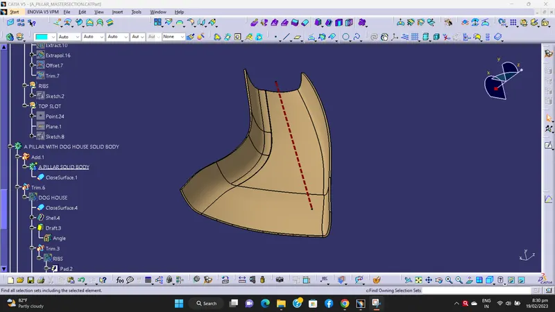
Now in part design workbench the final trimmed surface is converted into solid part by using close surface command.
8) Creation of Dog House with help of master section -
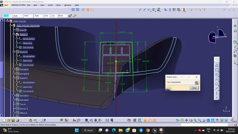
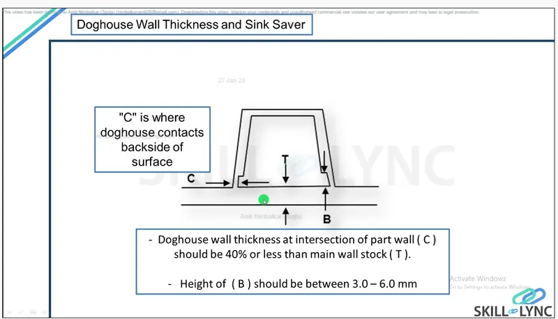
Doghouses are created by following the design rules. For this, the sketch is created from the master section provided. It is then made into a closed body and is made into a part model.
Shell operation is performed to get a hollow structure and then coring is done in order to avoid sink marks on the class A surface. Drafts are given for the surfaces as per design rules and proper fillets are also provided. As per the given master section, ribs and supporting features are also added to the doghouse.
Then, the doghouse is added to the main body. All the sketches used are iso-constraint.
We create Dog House in following procedure -
A) Dog house creation.
B) Side coring axis.
C) Coring side.
D) Ribs.
E) Top slot.
F) Draft analysis performance.
A) Dog house creation -
a) Sketch 1 -
b) Sketch 2 -
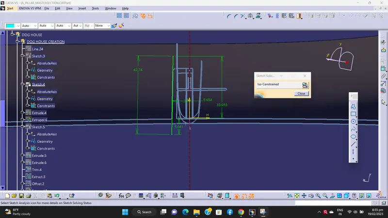
c) Sketch 3 -
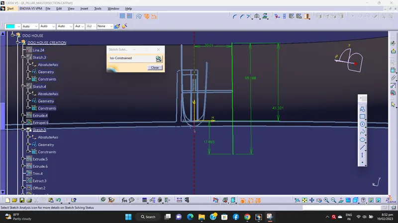
d) Dog house making solid -
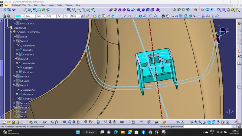
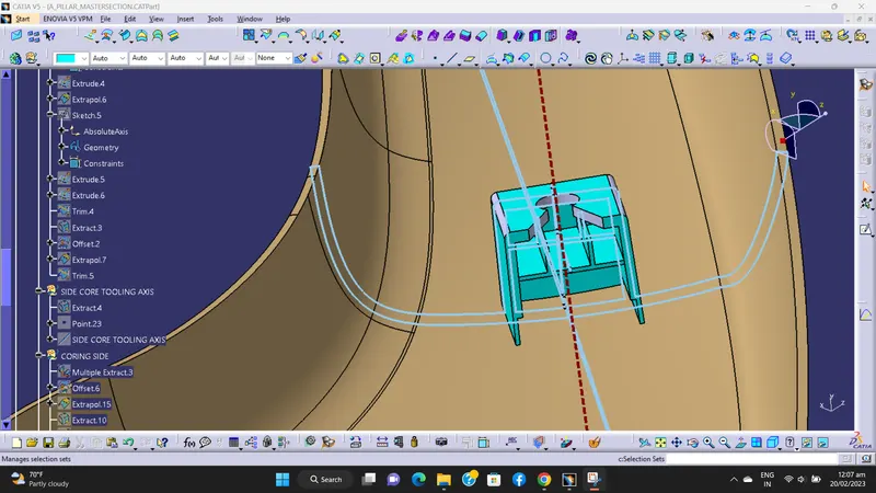
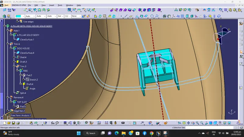
B) Side coring axis -
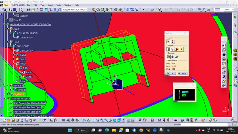
The side core axis is created to normal to the surface. The dog house inner walls and all the ribs will be created using the side core axis.
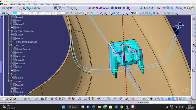
C) Coring side -
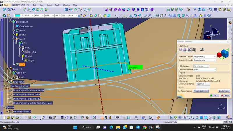
By following design standard for coring we created coring side.
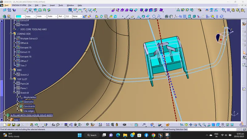
D) Ribs -
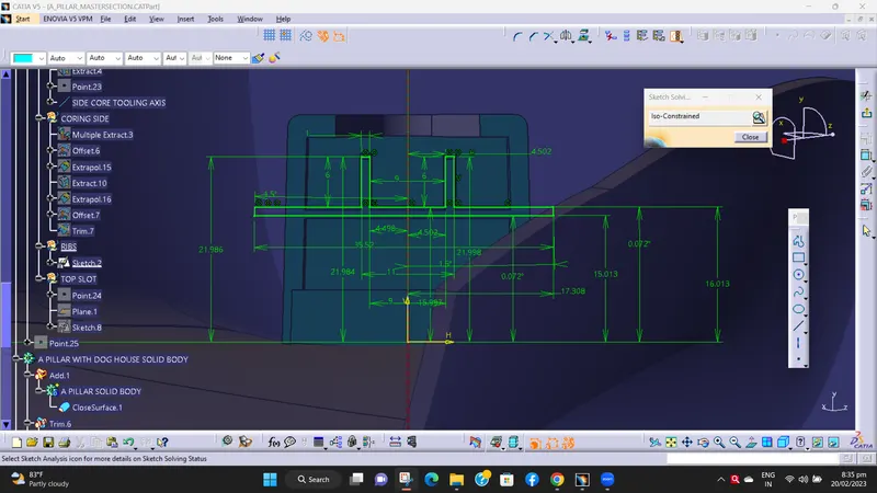
a) Sketch -
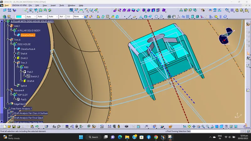
b) Ribs making solid -
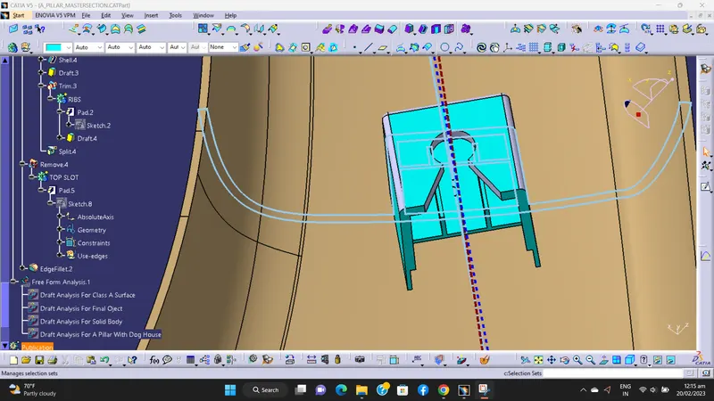
E) Top slot -
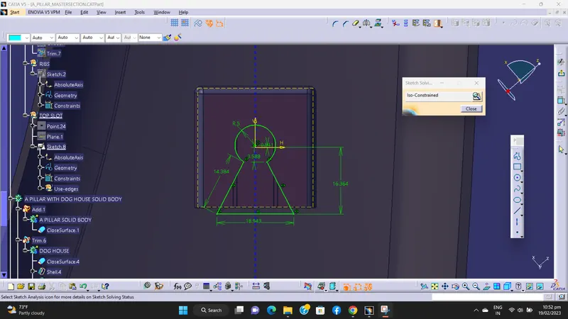
a) Sketch -
b) Used boolean operation REMOVE -
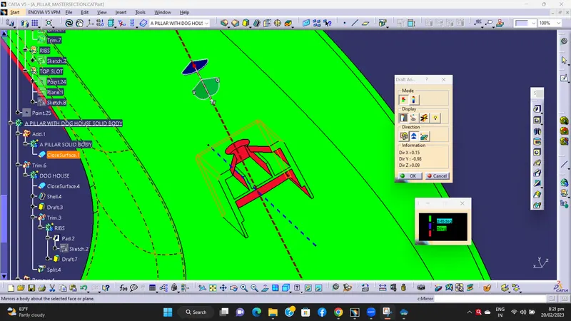
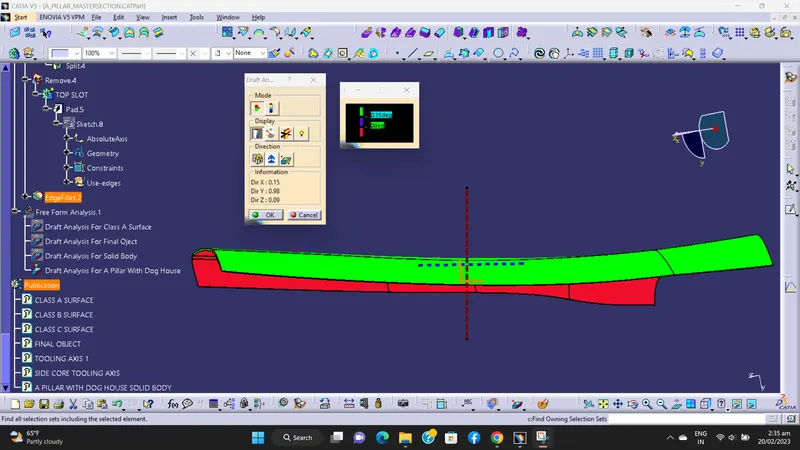
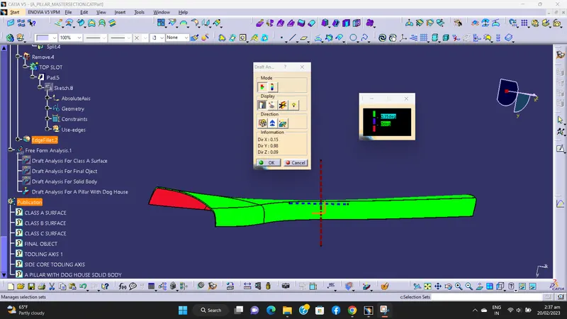
F) Draft analysis performance for Dog House -
a) Draft analysis performance with main tooling axis -
b) Draft analysis performance with side coring tooling axis -
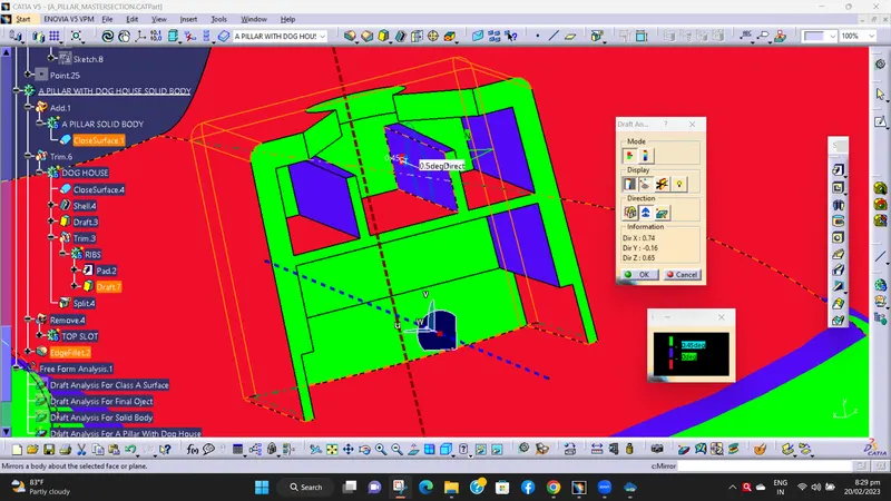
NOTE -
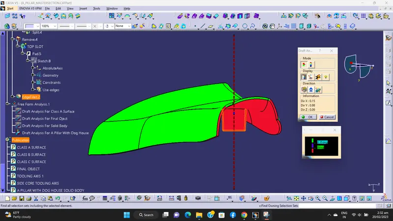
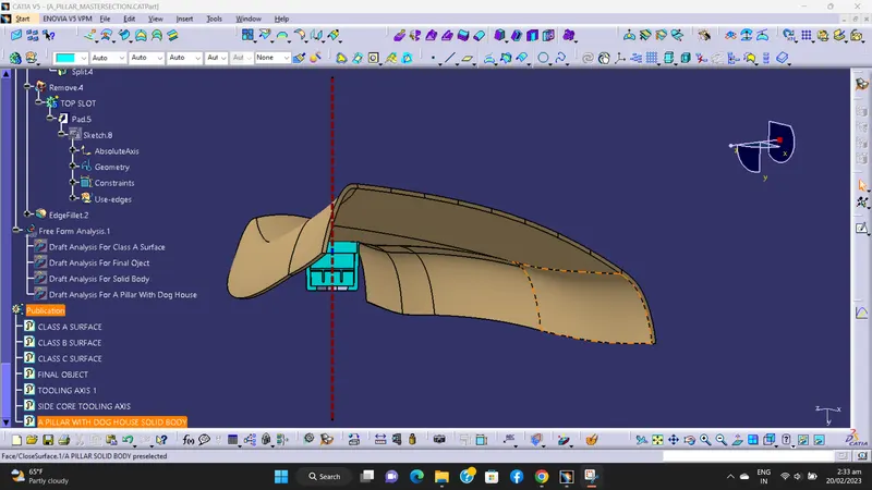
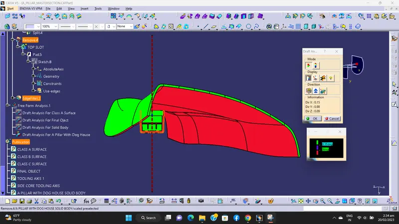
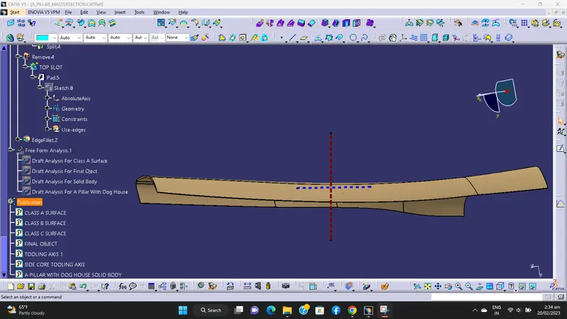
AS PER DISCUSSION WITH TECHNICAL SUPPORT MENTOR, DRAFT ANALYSIS FOR DOG HOUSE WITH SIDE CORE TOOLING AXIS IS NOT SHOWING ACCURATLY WITH 0.45 DEG ANGLE IN MY CATIA VERSION. THATS WHY I AM PERFORMING DRAFT ANALYSIS WITH 0.35 DEG ANGLE.
KINDLY REFER THE BELOW IMAGES.
Various Orientations -
1) Isometric view -
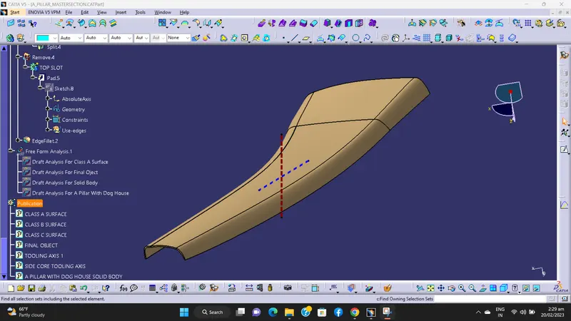
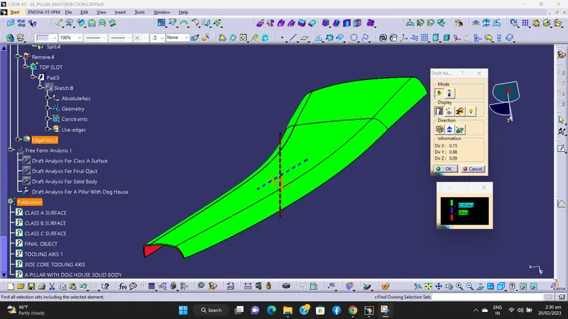
2) Front View -
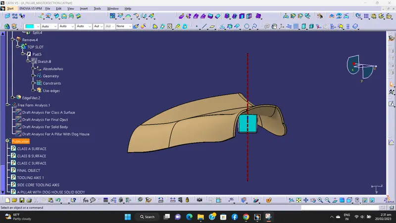
3) Back View -
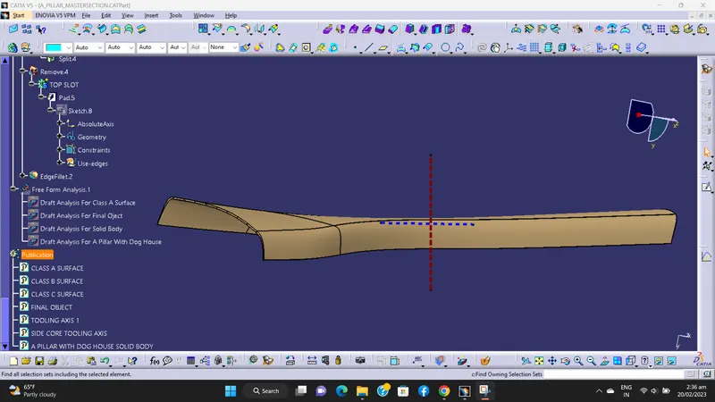
4) Side View RH -
5) Side View LH -
6) Top View -
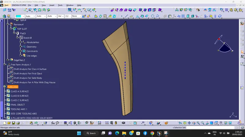
7) Bottom View -