Week 9 - Project - A pillar Design with Master Section
OBJECTIVE
A Component has to be created in closed body along with A,B and C Surfaces,creation of Tooling Axis, feature attachments according to given master section.
REQUIREMENTS:
Software Knowledge about CATIA V5.
PROCEDURE
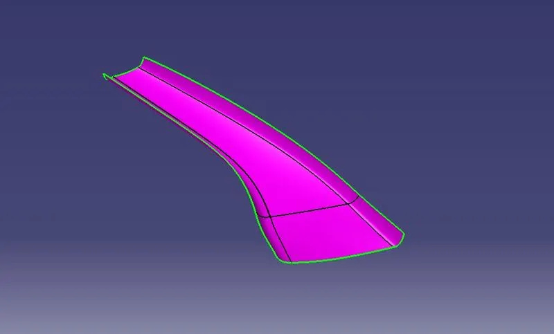
Open the given class A surface file, with Master Section.
Tooling axis creation
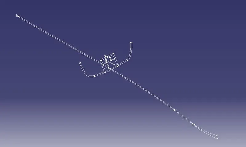
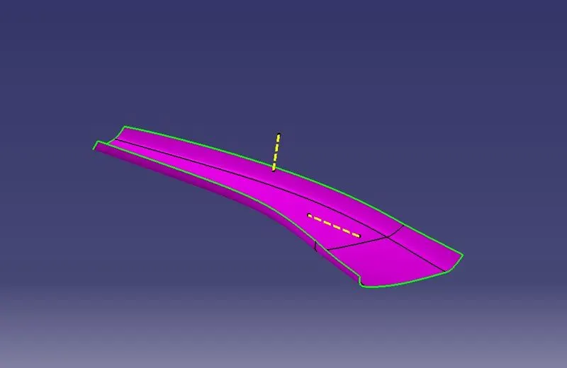
The tooling axis direction refers to the direction in which the mould opens and shuts. Before defining the tooling axis, make sure the surfaces are connected and that there will be no gaps between them. Please make sure to place the tooling axis on a surface with a hole or one that is flat when building a tooling axis. In order to build the dummy tooling axis using the intersect method by creating a bisecting line, first create a point in the centre of the base surface using the point on the surface command. Then, create an intersection for the surface and extract the reference lines.Draw lines that are aligned with the extracted lines using the line command, extending them to the necessary length.
DRAFT ANALYSIS OF CLASS A SURFACE
To perform draft analysis, click on Insert >>Analysis >> Feature Draft Analysis.
To tackle this issue, CAD engineers uphold a common design rule for plastic moulds or dies, which ensures that there are no issues with ejecting plastic components. Therefore, every plastic component is designed with a minimum of 3 to 10 degrees of draft angle.
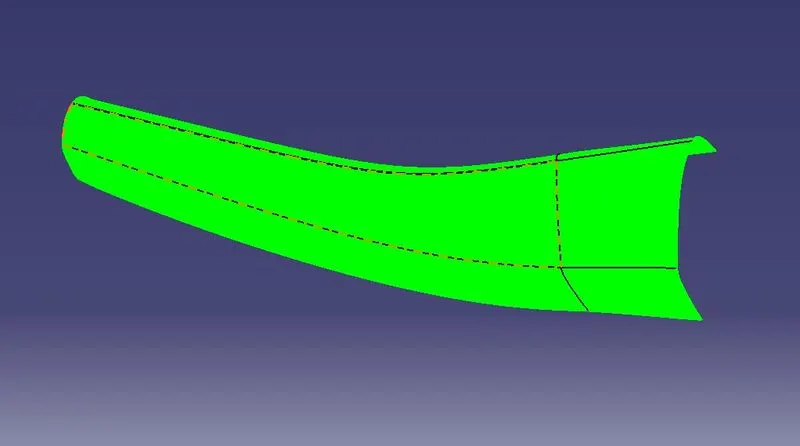
Draft analysis is performed on the given Class-A surface, and it is clearly observable that there is no negative draft on the surface.
CLASS B SURFACE
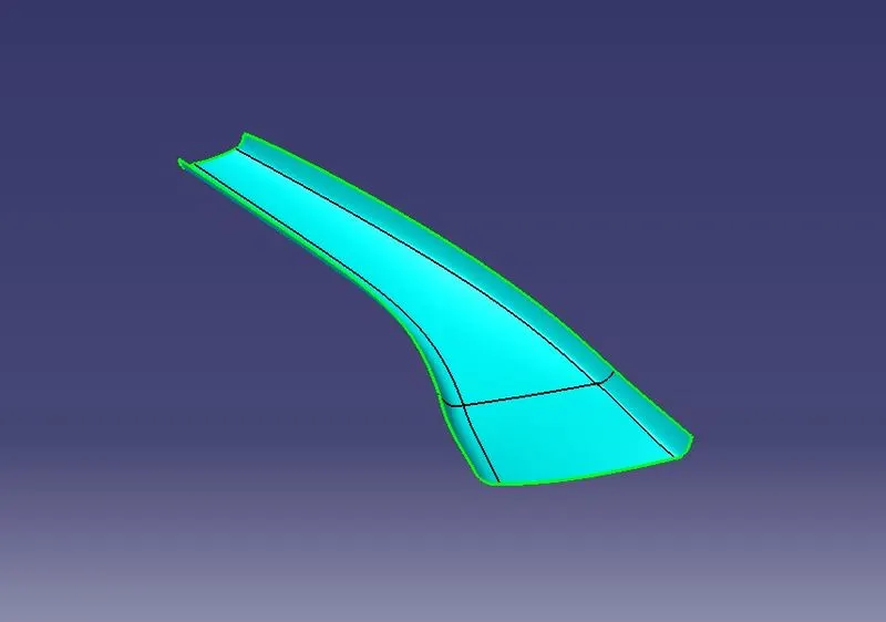
Extraction of the Class A surface without the fillets, extrapolation of the fillets to link them, offset of the surface to 3 mm thickness, and formation of the Class B surface.
CLASS C SURFACE
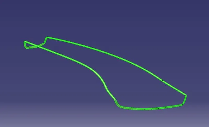
By extracting the boundary of the class - A surface, the surface required for the class - C is obtained, using the smooth curve option a smooth surface can be obtained by sweeping the line towards the direction of the tooling axis.
OUTPUT
Join Class A and Class C surface using join command and make sure there's no gap between and we can check using boundary command for the gaps.
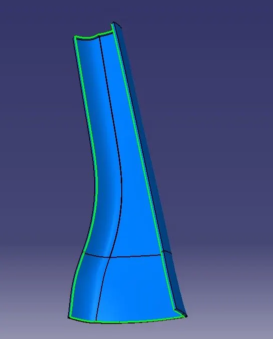
Then trim the joined A and C surface by B Surface to obain the final surface.
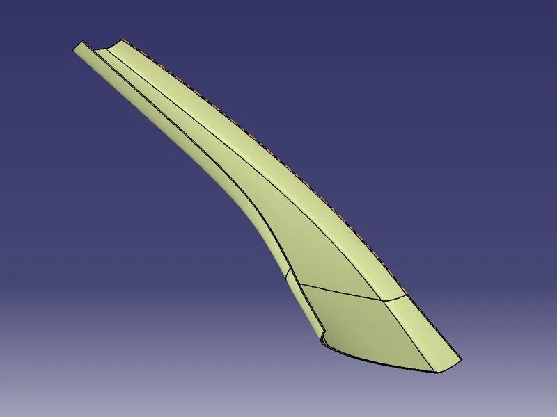
Open it in part file and use closed surface command to turn the final output into manufacturable product design.
DOG HOUSE
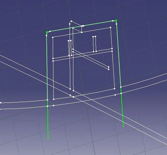
By extracting required lines first and creating sketch by isolating them and making it fully defined.
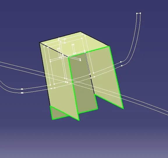
Extruding those lines and make sure the extrude coincides with master section, trim the surfaces and obtain the required like in the above image.
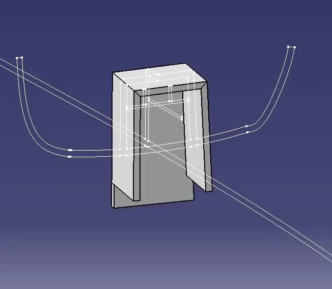
change to part body bench and thicken by 2.5mm value. Constantly observe the model and master section that is in sync.
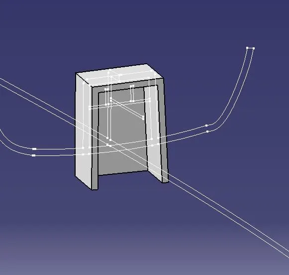
Comparing earlier image the front face had some intersecting lines on front face of the object, so to eliminate them using split and other planes for front face, also the bottom one had long extention compared to other two sides In order to correct that i have used another plane as intersection to clear them. So the Dog House looks good by improvement work. It can be seen in above image.
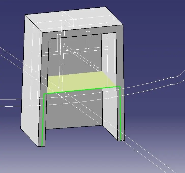
further I took Multiple Surface of inside as one and offset them outside so that I was able to get the surface bisecting the thicken part. After that i am extracting Top Surface of Dog House and Offseting According to measurements of master section and placing it. I needed 12 mm of height so corresponding to that i have prepared the inside surface byusing trim command.
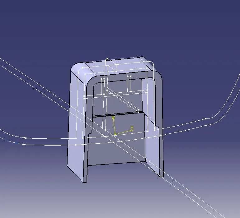
So I got the bottom Portion right and passing the minimum thickness requirement.
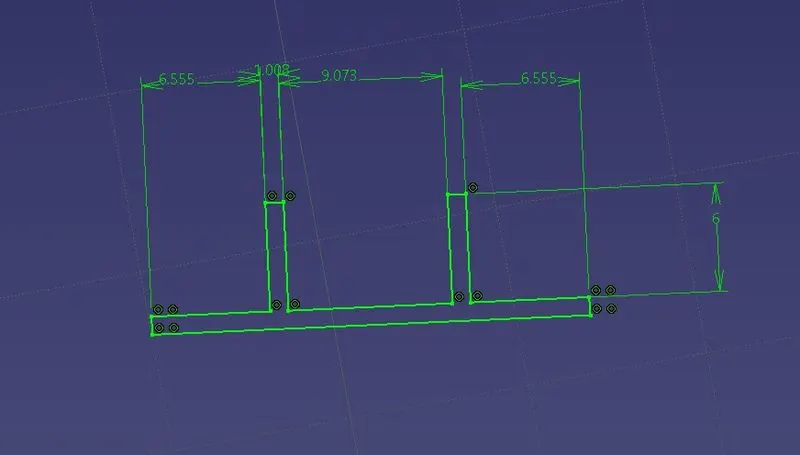
After that I'm extracting the required sketch from master section and isolating them and giving dimensions and making it fully defined, so i am expanding little bit on sides so that it can merge with the thicken model. Once the sketch done i did pad.
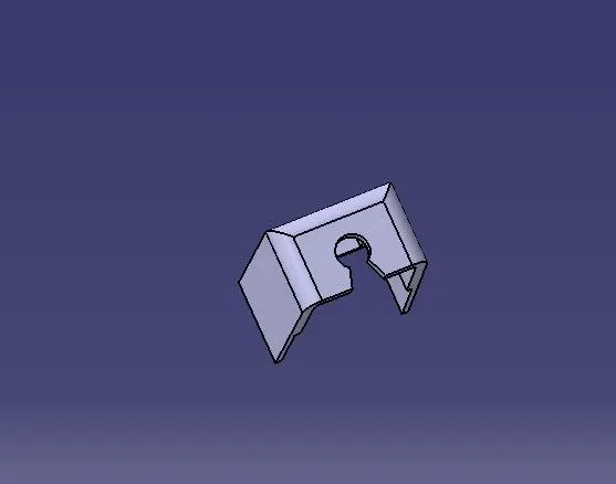
Also Draw one more sketch on top and make sure its fully contrain. extrude and split it so the final dog house would be like the imag below.
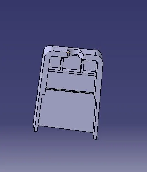
DRAFT ANALYSIS FOR FINAL OUTPUT
Go to the Direction block in the draf analysis toolbar and select the "Use the compass to set the new current draft direction" option to align and fix the compass to the tooling axis (or just click on the compass symbol). Bring the compass to the surface at this point, align it with the class A surface's tooling axis, and then click the lock icon next to it in the direction block. We can complete the draught analysis process by clicking "ok" on the toolbar for draft analysis.
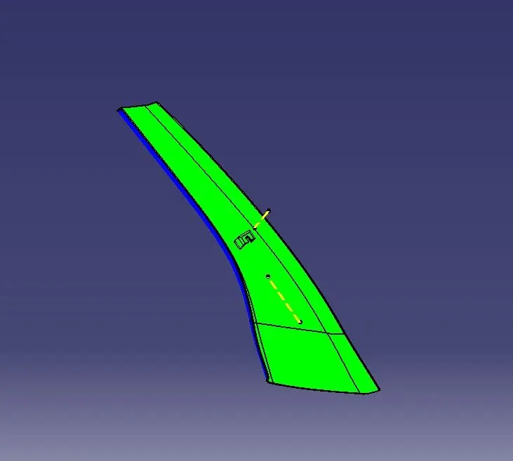
The draft was tested on 1.4 draft value and the model showed green almost everywhere, the sides on dog house were clearing but not in inside, this first test was done using main tooling axis so this maybe reason for not clearing.
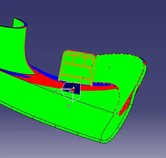
using side tooling axis the front face of the dog house was clearing at 1.4 draft value and inside the sides were not clearing this maybe because of absence of draft value during the construction. If its drafted then it may show clear result and It would have passed.
FINAL MODEL
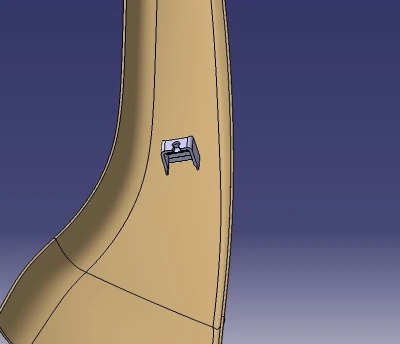
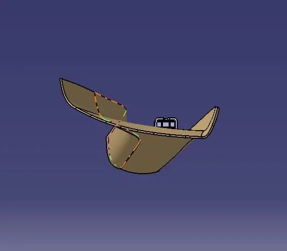
The trim was success.
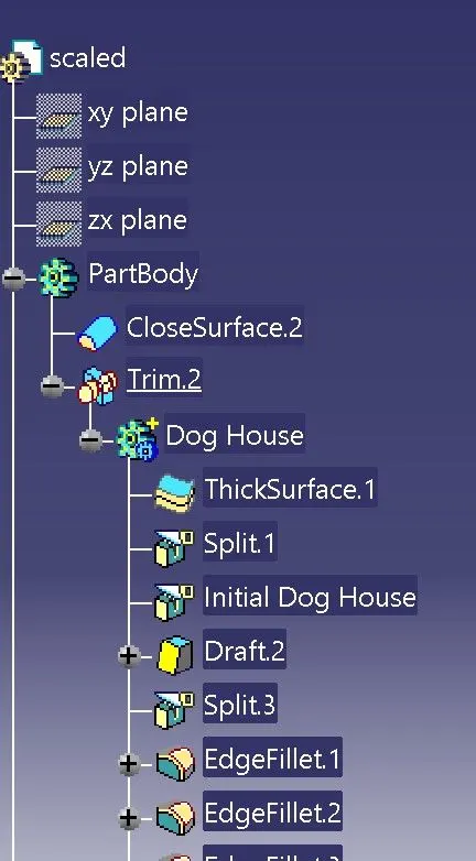
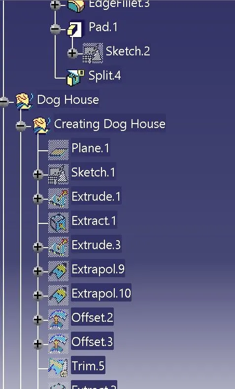
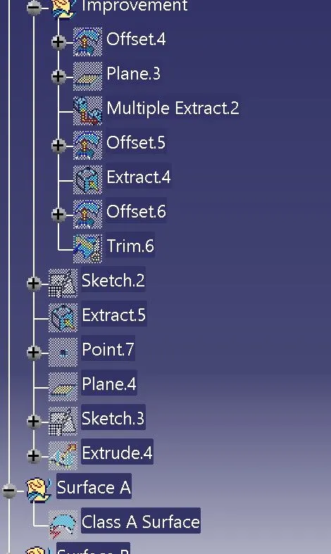
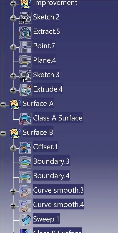
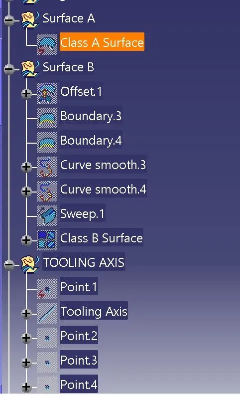
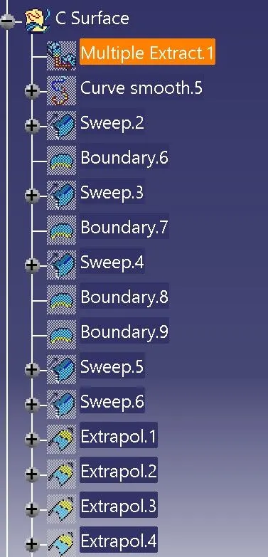
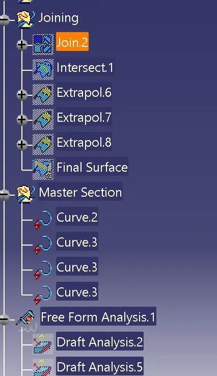
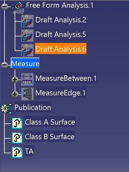
FEATURE TREE FOR MODEL
CONCLUSION
Thus the A Pillar Model is Built according to master section, proved to be a closed surface, Tooling axis,B and C Surface were created, draft analysis was performed.