Week 9 - Project - A pillar Design with Master Section
Given class-A surface
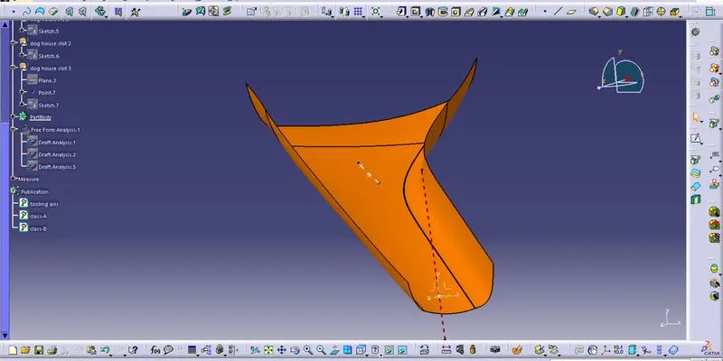
Creation of tooling Axis:
To create a tooling axis, insert a point by taking the reference surface as class-A. Insert an axis system using the point. Extract the boundary of the class-A surface. Using the boundary draw two lines coinciding with the boundary. Use the bisecting line to create a line using the two lines. The Sketch is shown below.
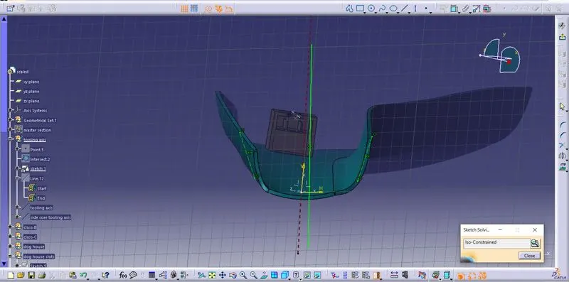
Insert a reference line using the inserted point and give the direction perpendicular to the class-A surface. Using bisecting line option create a line using the sketch output line and created reference line. This output is the final tooling axis.
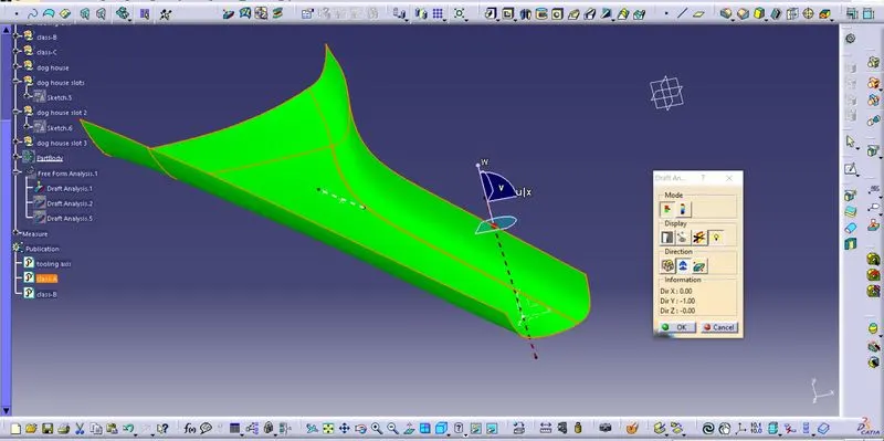
Once the tooling axis is created, Perform a draft analysis to check whether the given class-A is feasible or not. The draft angle provided is 3deg. The draft analysis is shown below.
Creation of class-B:
Using the class-A surface we extract the surface patches of class-A, join them and offset them to a distance of 2.5mm.
The obtained class-B is shown below.
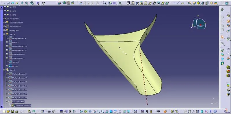
Once we got class B, we create the class-C surface, Unhide the class-A, and extract the outer edges of the class-A surface. Using the boundary we use the sweep option and create the class-C surface. The obtained surface is shown below.
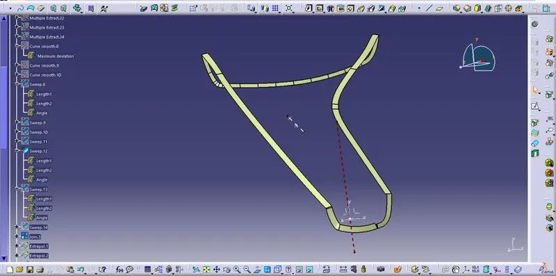
After getting the class-B and class-C surfaces, we trim both surfaces. Once we trim both these, we join the class-A surface using the join command. To check whether the body is closed or not, use the boundary option. If there is no boundary then the part is completely closed. To form this as a closed body, go to the part workbench and use the closed body option.
Creation of dog house:
Using the given master section we find the thickness of the dog house. Using the master section as a reference we create the sketches of the dog house. The images are shown below.
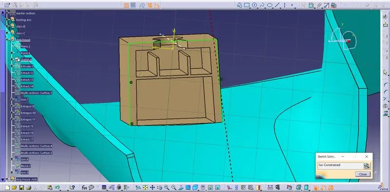
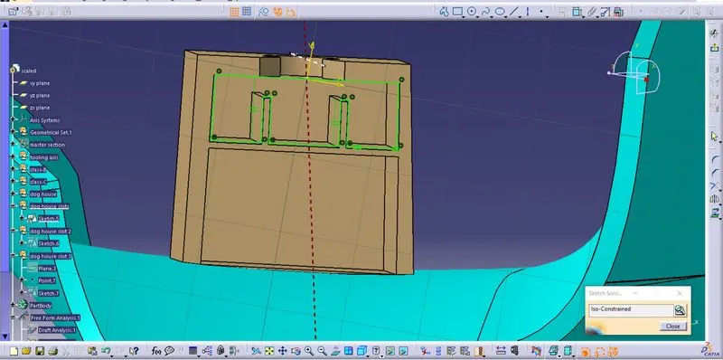
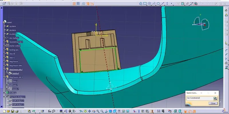
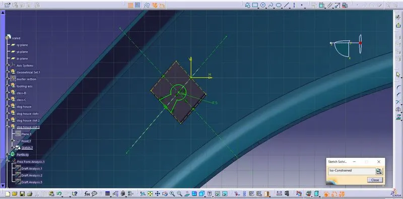
After we create the sketches, we go to the part workbench and use the pad option. Once we pad all these sketches use perform boolean operations like remove and add. In the areas where there are slots, we use the remove option and add option to add the dog house to the solid component. Once we have added we get the final component that is created using the master section.
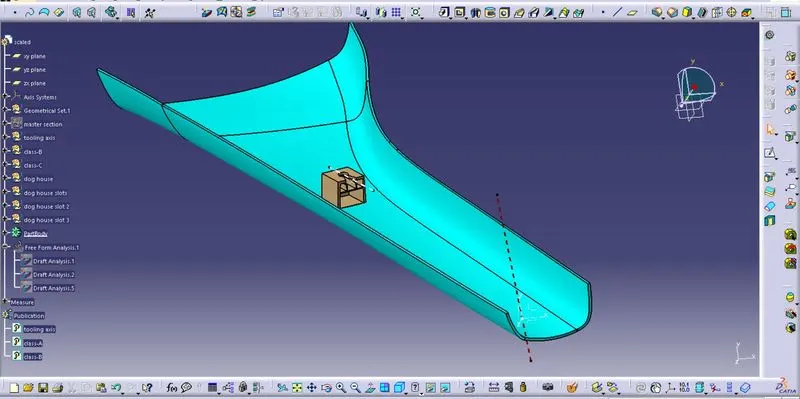
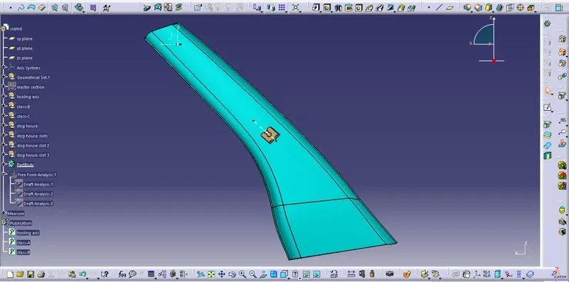
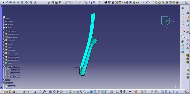
Different views of the final component namely isometric view, front view and top view.
Draft analysis:
Using the main tooling axis the thickened component and the dog house outer part are analysed with the minimum draft angle of 3deg.
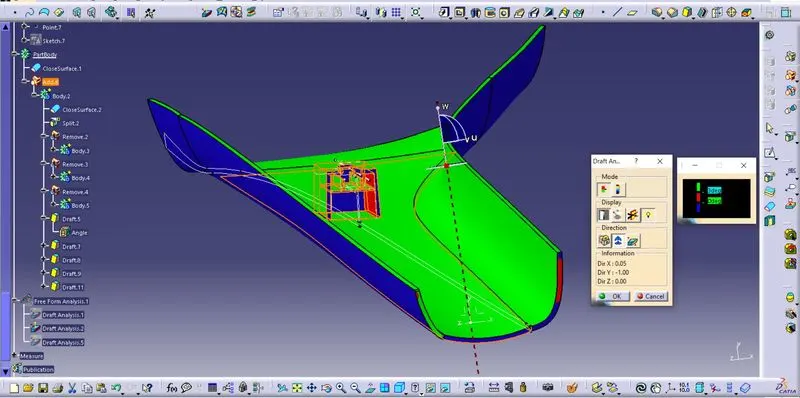
The front face and right side face of the dog house has blue regions. To solve this we have tried drafting the faces with a draft angle ranging from 1 to 3 deg. At 1deg, the faces turned into red colour but the shape of the dog house is entirely changed. The thickness of the component is also reduced. Hence the faces are drafted with the draft angle of 3deg.
Draft analysis using the side core axis:
To perform the draft analysis on the inner walls of the dog house we need to create the tooling axis in the horizontal direction. This tooling axis is created because the side core moves in this tooling direction. The draft analysis is shown below.
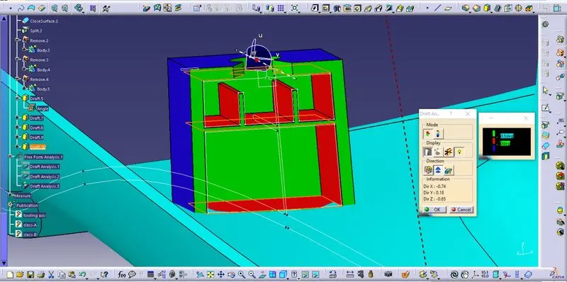
The draft analysis is made using the draft angle of 0.5deg. The inner walls have been drafted with 0.5deg draft and we achieved the red colour region from blue colour. If the walls are further drafted the thickness of the walls is decreased. So the walls are not drafted further and with a 0.5deg draft, the inside walls have passed the draft analysis.
Conclusion:
Using the given class-A surface, class-B and class-C are created and a solid body is formed. Using the master section the dog house is created and draft analysis is performed using both the main tooling axis and side core axis.