Week 9 - Project - A pillar Design with Master Section
REPORT
AIM
To Create the A-Pillar Plastic component through the given Class-A surface and create a Doghouse feature from the references from the given Mastersections.
TOOLING AXIS CREATION
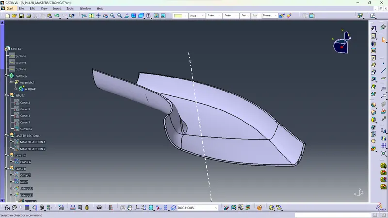
The starting will be from the creation of tooling axis. we need to select the tooling axis so as it is the optimum orientation for the component production in real life. Generally, first we look if its okay for the tooling axis to be in the XYZ directions. If thats not possible, then we will look for large, flat surface and take the tooling axis normal to the surface. If that is also not possible, then we will create tooling axis with bisecting method.
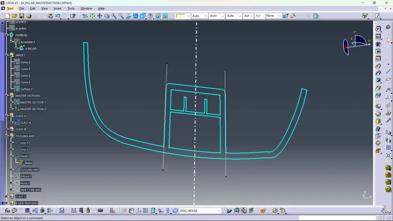
Here, the master section falling through the dog house is considered and a bisecting line is created from the master section lines falling through the drafted surface of the dog house.
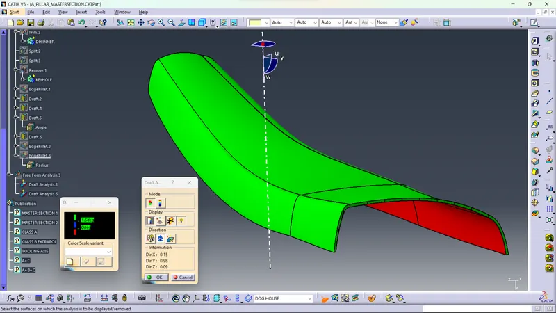
DRAFT ANALYSIS (CLASS A)
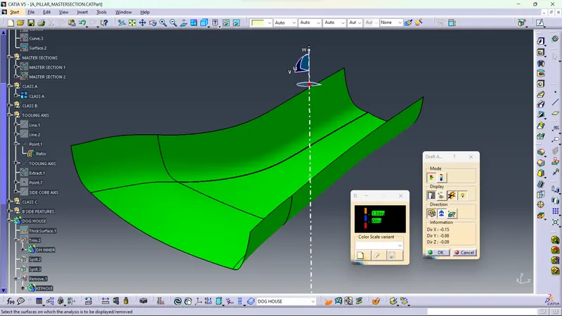
Click on the Feature Draft analysis icon.
Use the compass to Select the tooling axis as the direction.
B Surface Creation
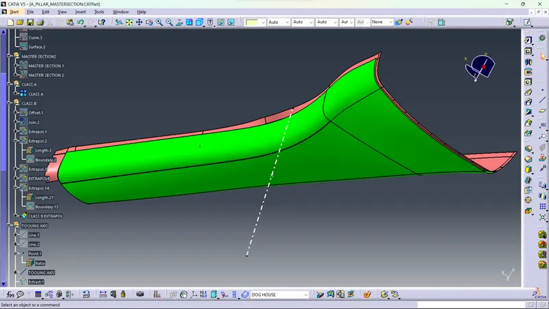
The specified thickness for the component is 2.5mm. Offset the class A surface 2.5mm in the inside direction. Some of the sub elements will not be offsetted very well. Such areas needed to be extracted individually and offsetted.
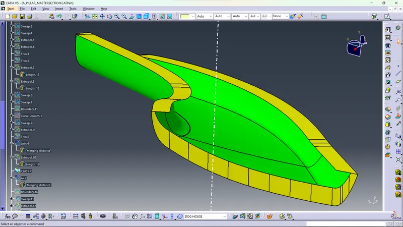
Class C surface creation
Trimming
The class A surface and class C surface is trimmed and then then it is trimmed with the class B surface to create a closed surface.
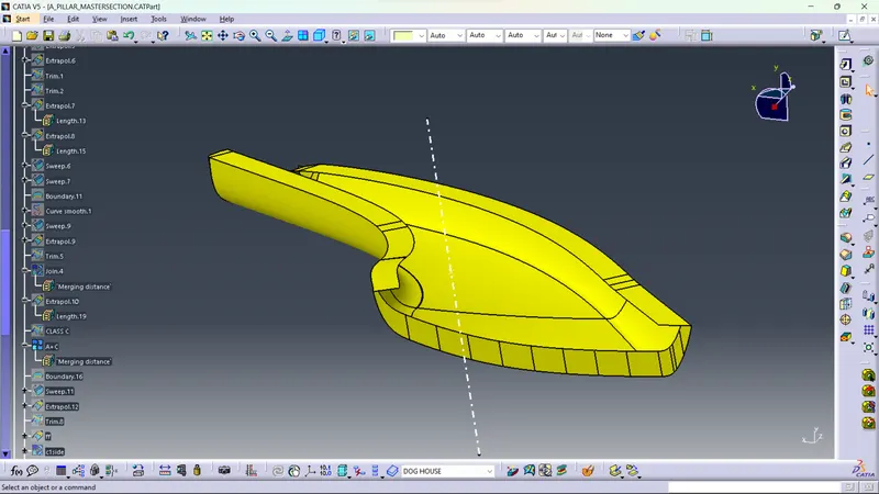
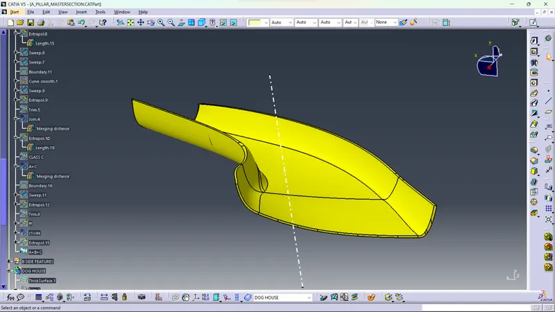
Solid Body Creation
Switch to Mechanical Part Design Workbench and select the closed surface operation in the surface based features. Define the part body and select the closed surface. The solid body wiil be created.
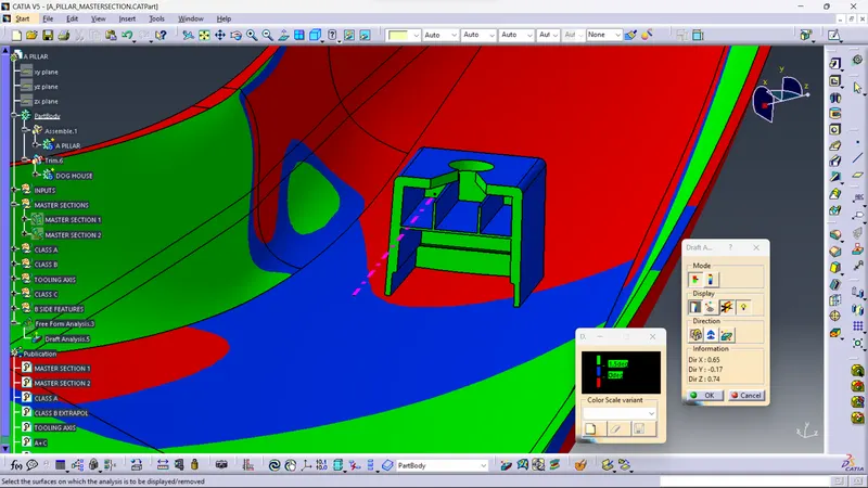
DRAFT ANALYSIS (PART BODY)
Click on the Feature Draft analysis icon.
Use the compass to Select the tooling axis as the direction.
B SIDE FEATURES CREATION
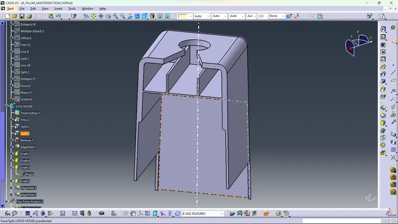
DOG HOUSE
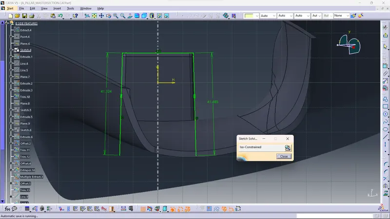
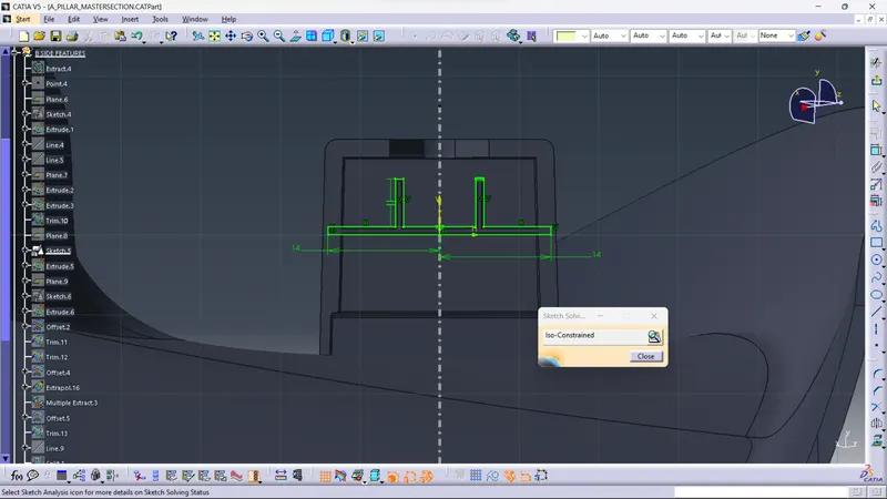
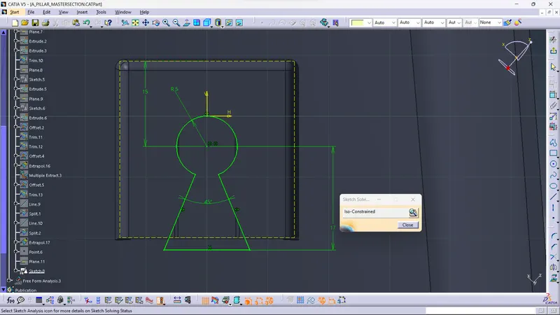
SKETCH
DRAFT ANALYSIS
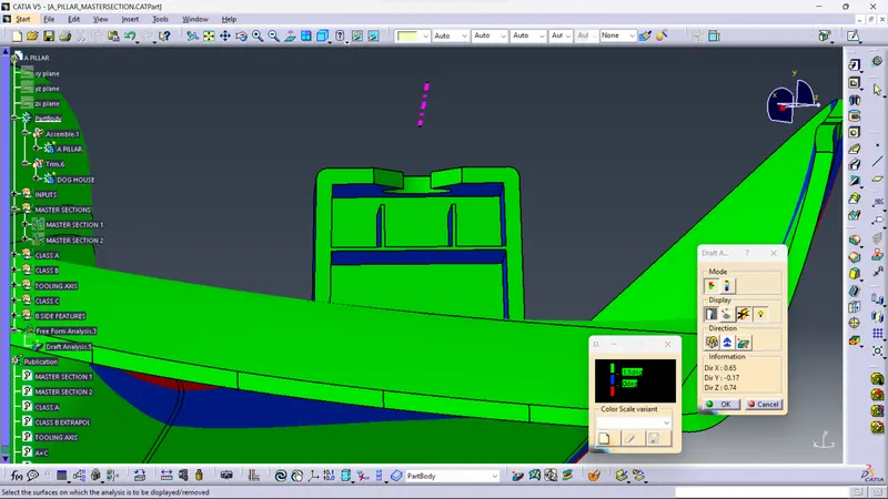
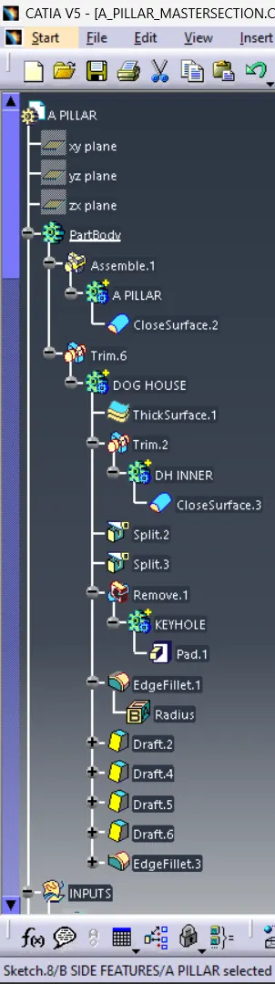
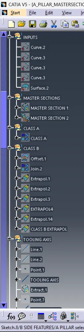
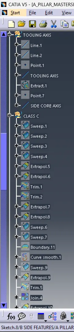
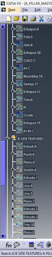
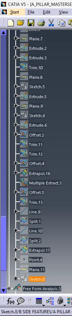
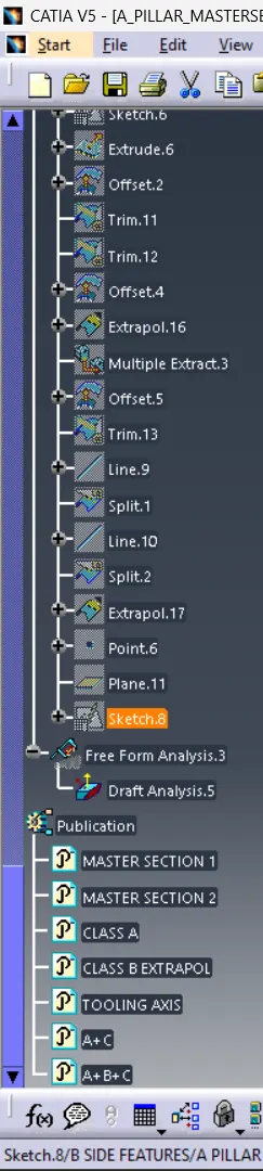
TREE