Week 9 - Project - A pillar Design with Master Section
DESIGN OF THE A PILLAR
AIM:
To create the A PILLAR component through the given Class-A surface and to create the dog house for the Drill Handle with considering the design rules.
SOFTWARE USED:
Catia V5
DESIGN PROCEDURE:
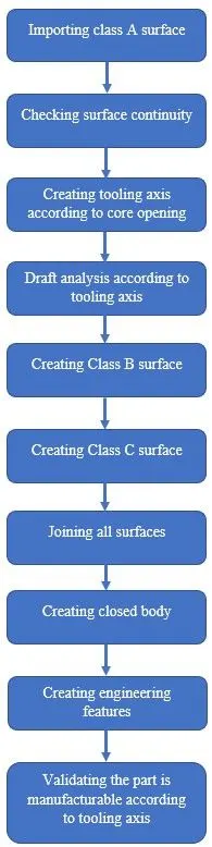
IMPORTANCE OF TOOLING AXIS:
The Tooling Direction is the direction that the mould pulls apart. The mould is built into two separate pieces. You have a Cavity side and you have the Core side. The Core pulls apart from the Cavity and that's the Dyeline or the Tooling Direction. There are different methods to find out the tooling direction. Here we are using bisecting method to find out the tooling direction. We can use any method the ultimate aim is to reduce the cost of manufacturing by reducing the complicity in manufacturing the component.
- It is the direction in which the component will be ejecting after the molding process is completed.
- The direction of tooling axis should clear the maximum portion of the part.
- It should be selected in such way that number of side cores will be minimum as it will add more cost to the process.
IMPORTANCE OF DRAFT ANGLE:
A functional part for injection molding has to have drafts facing both cavity and core sides to reduce the risk of damage to the parts and ensure ejection. As the molten plastic flows into the closed die and fills the cavity, the material shrinks inside the mold upon cooling and as a result grips the core. Draft angles should be at least 3° to facilitate the part ejection.
- Reduces the chance of damage to the part due to friction during release.
- Reduces wear and tear and chances of damage to the mold.
- Ensures a uniform, smooth, unscratched finish when required.
- Ensures the integrity and uniformity of other surface finishes and textures.
- Reduces overall cooling time by lessening or eliminating the need for unconventional ejection setups.
WORKBENCH AND TOOLS USED:
CATIA V5 - Generative shape design
- Extract
- Multiple Extract
- Extrapolate
- Join
- Trim
- Spilt
- Offset
- Boundary
- Edge fillet
- Intersection
- Sweep
- Fill
- Multi section
- Close surface
- Translation
- Feature Draft Analysis
DESIGN TREE:
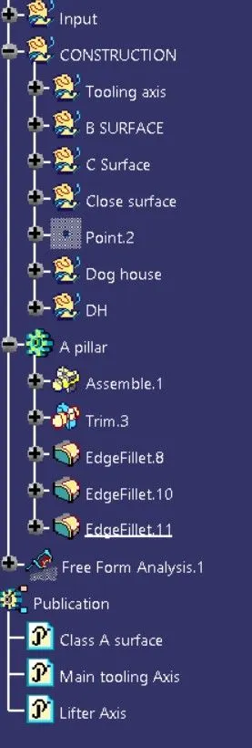
METHOD:
Step 1: Importing the A PILLAR and Check Class A Surface design file:
After receiving the class, A of the A PILLAR check for the connectivity of all surfaces on it. Use Join operation, boundary operation and disassemble. The check is over if any discontinuities do not arise. Delete the operations after the check.
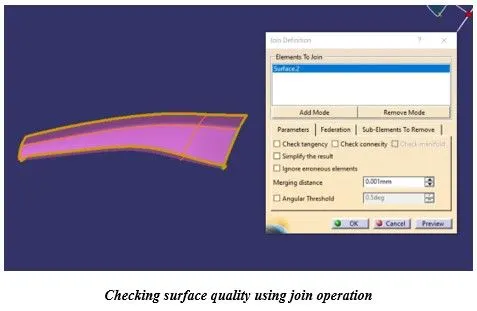
After importing the class ‘A’ surface, we need to check the connectivity between the surface with merging distance 0.003 mm.
Step 2: Determine Tooling Axis:
Create a Tooling Axis along the best possible direction as per the Class A (normal to the surface) as shown below.
In this part there is need of lift core because of dog house presence. So, tooling axis for side core is provided.
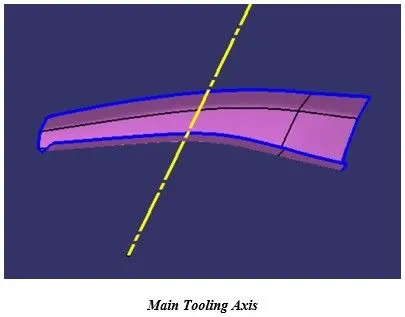
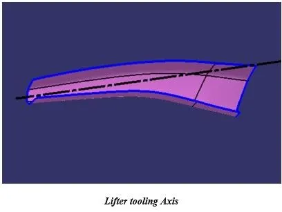
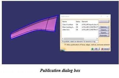
Now that the Tooling Axis is created let's Publish the Tooling Axis and the Class A Surface for quick access.
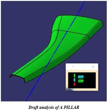
Step 3: Draft Analysis:
Change View Mode Customization to Material mode
Go to INSERT > ANALYSIS > FEATURE DRAFT ANALYSIS and move the compass to the Tooling Axis. Change the range to 3°. Apply the settings.
Uses the compass to define the new current draft direction.
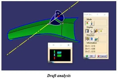
On Class A surface, Draft analysis along tooling axis were failed on some surfaces thus need to inform the class A designer.
Step4: Class B Surface:
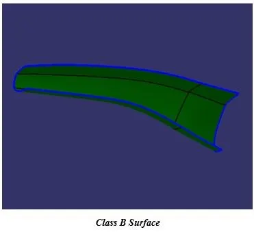
Consider the thickness of the component as 2.5mm. Now we need to create a B surface which will be similar to the A surface at an offset value of 3mm.
First, we are creating offset of the class A surface.
Once the surfaces are offset by its thickness, then examine the continuity and repair the surface.
Now repair the continuity issue and build smooth surface.
Towards the last part of creating the Class B Surface, we will join the Final trim part with the part to obtain the below Surface B.
Once all the surfaces are created trim these surfaces to form a Class B surface and give the appropriate fillets to form a Class B surface.
Step5: Class C Surface:
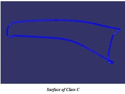
To create a Class C surface, first, extract the boundaries of the Class A Surface.
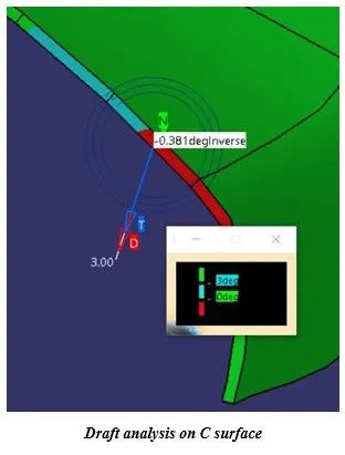
Now using the Sweep option create the surface. To perform this operation, go to the Toolbar > Sweep > Profile type > Line > Subtype: With draft direction > Guide curve 1- (select the extracted boundaries) the in-Draft direction (select the tooling axis) angle and length as 3° and 4mm respectively and click ok
The same process will be done for the holes, extracting the boundaries and using the sweep operation to form a surface.
Step 6: Joining the all surfaces:
Now we will use the Join command to join all the 3 Sweep operations that we have created. This will give us the Class C Surface.
After the creation of Class, A, Class B and Class C surfaces, we need to join Class A and Class C surface to form a new surface. Then trim the joined surface with Class B surface to form the final required surface.
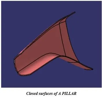
Step 7: Closed body of A PILLAR:
Now that we have the required surface, we can make a solid body out of it. To make a solid body we will go to the Part Design section over there we will use the Close Surface tool to make a Solid Body.
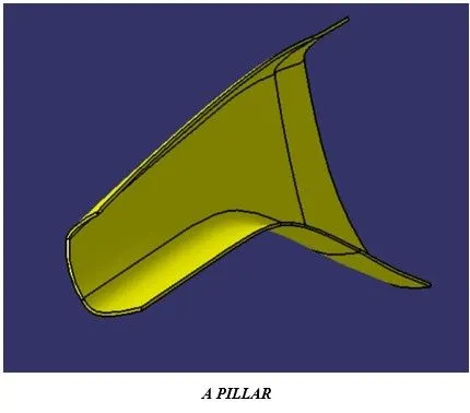
Step 8: Creation of Engineering Features:
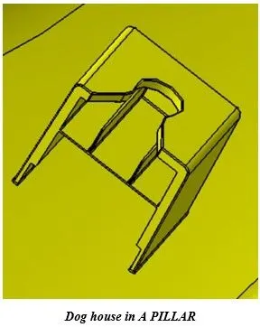
DOG HOUSE:
Purpose
Dog-House is the Engineering supporting feature used in Plastic Designing.
- It helps to avoid sink marks.
- It also provides enough strength to join different surface having large distance between them.
Design Guidelines for Dog house:
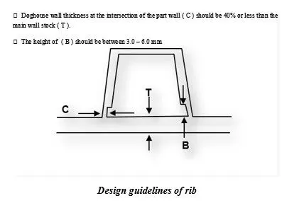
- Draft
- Thickness
- Height
- Spacing
- Thickness at the Top
- Optional Radius
- Design suggestions
- Dog-House wall thickness = 0.4*T (T=thickness of component)
- Height(B) = 3 to 6 mm
- steel Width/Height ratio = 3:1
- 'C' is where Dog-House contacts the backside of the surface.
Step 9: Validation of the A PILLAR:
Change View Mode Customization to Material mode
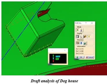
Go to INSERT > ANALYSIS > FEATURE DRAFT ANALYSIS and move the compass to the Tooling Axis. Change the range to 3°. Apply the settings.
Uses the compass to define the new current draft direction
RESULT:
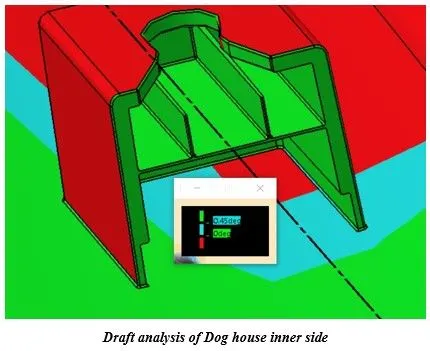
A pillar part and dog house outer can be manufactured using main tooling axis which cleared 3degree and 0.5degree respectively in draft analysis.
Dog house inner can be cleared using side core and it passed draft analysis using side core tooling axis.
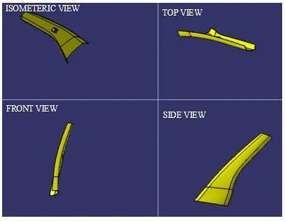
Hence, the A PILLAR component through the given Class-A surface has been created along with Dog house according to the design guidelines.