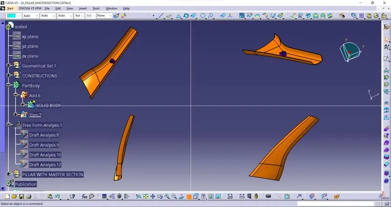
Week 9 - Project - A pillar Design with Master Section
Week 9 - Project - A pillar Design with Master Section
AIM:- The main objective of this challenge is to understand the given master section to create a solid body and B-side features for a given class A surface, by considering all the design parameters.
FIRST CHECK A-SURFACE:-
Before starting the creation of the class B surface we must ensure that the given class A surface is properly closed and the surface continuity is proper. This can be done either with the help of the join operation or by using the boundary feature.
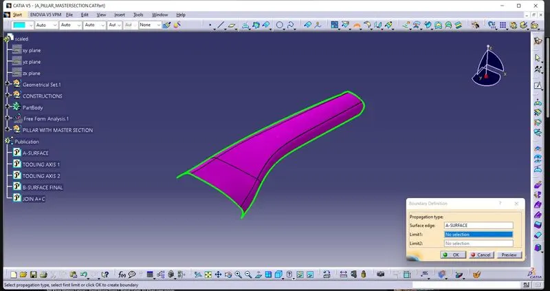
TOOLING AXIS:-
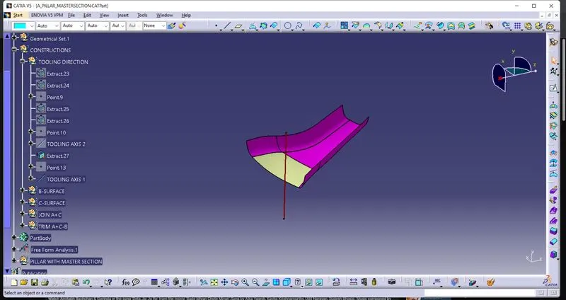
The Tooling Direction is basically the direction that the mold pulls a part. The mold is built in two separate pieces, basically. You have a Cavity side and you have the Core side. The Core pulls apart from the Cavity and that's the Dye line or the Tooling Direction.
- After analysing visually for the best possible tooling axis, an axis system is created on the centre of one of the surfaces of the door trim.
- The main tooling axis is created normal to the y direction
- I could have draw the tooling axis with the help of bisecting method but when i created that i found an error in A-surface when apply the draft on surface with that tooling axis thats why i used the normal method to creat a tooling axis.
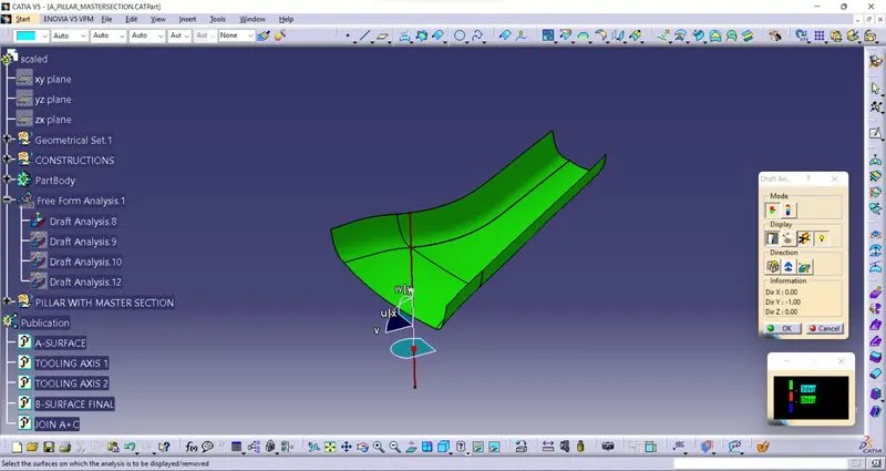
DRAFT ANALYSIS:-
With bisecting method tooling axis:-
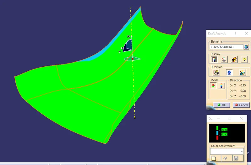
With normal method tooling axis:-
B-SURFACE:-
To create the class B surface initially, I measured the thickness of the master section (2.5mm). I offset the class A surface 2.5mm to the inside direction. The styling fillets on the class A surface are not offset properly, it created the patch on the offset surface. I used the sweep command to close the patch on the offset surface.
Offset patch:
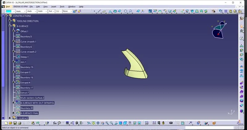
AFTER USING SWEEP COMMAND
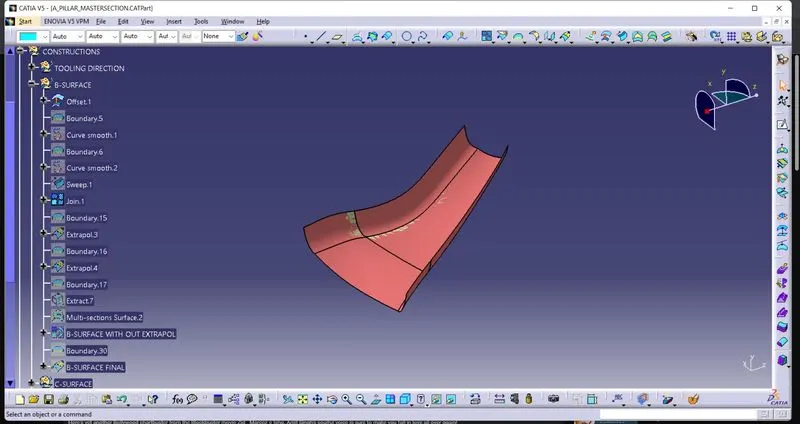
FINAL B-SURFACE:-
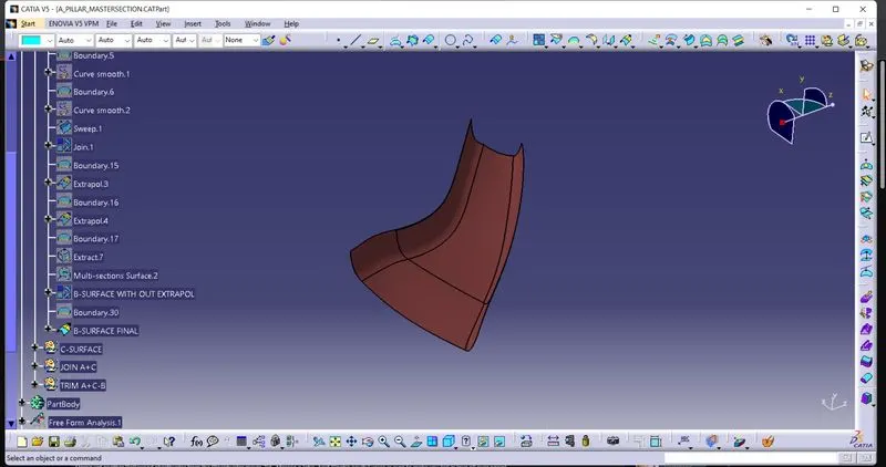
C-SURFACE:-
- Extract the boundary from the class A surface using boundary command.
- Using disassemble tool to divide the boundary as the boundary contains domains.
- Use sweep command > choose profile type line > subtype as with draft direction > choose guide curve and draft direction > draft angle as 3 degree > preview for some area use reference surface command with draft angle 90 degree.
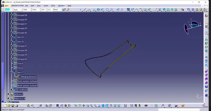
JOIN A+C SURFACE:-
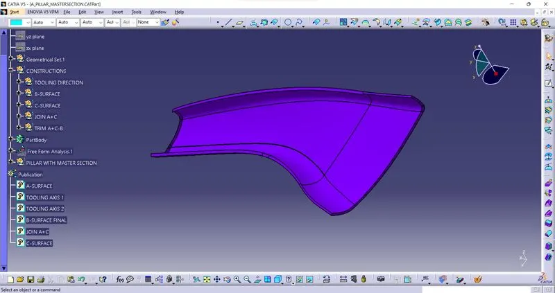
TRIM B SURFACE FROM A+C SURFACE:-
The final trim is created by joining the Class A and C surface and finally trimming it with the Class B surface. The combination of class A, B and C surface is then converted into a solid with closed surface command in the part workbench.
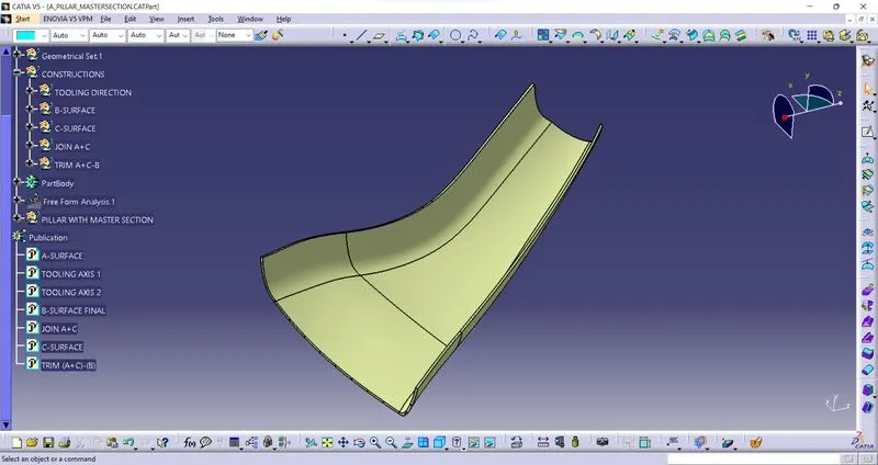
SOLID BODY:-
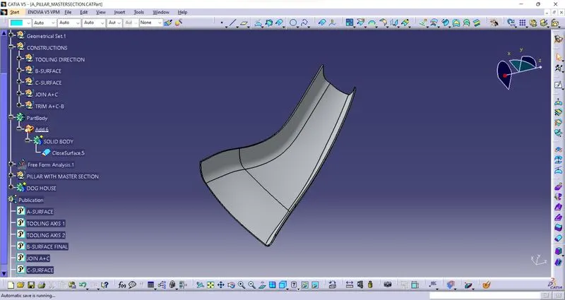
DRAFT ANALYSIS ON SOLID BODY:-
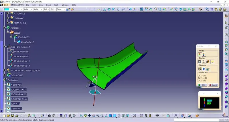
ENGINEERING FEATURE WITH THE HELP OF MASTER SECTION:-
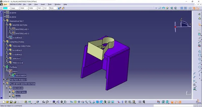
DOGHOUSE:-
- To create the dog house on the B-side, I extracted the lines on the master section and and use sweep command to creat the doghouse outer shell.
- I extracted the faces which are required to create the shell for the dog house, and I fill the surfaces with each other as per the master section dimensions.
Dog house outer shell:
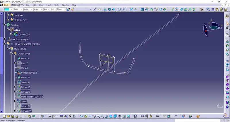
SWEEP:-
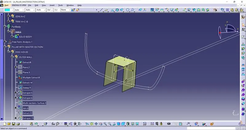
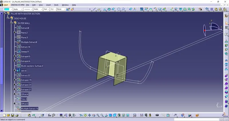
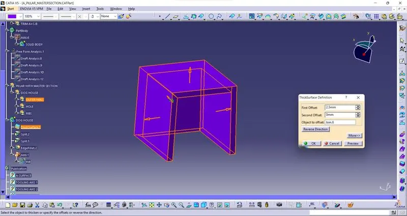
I thicken the shell for 2.5mm.
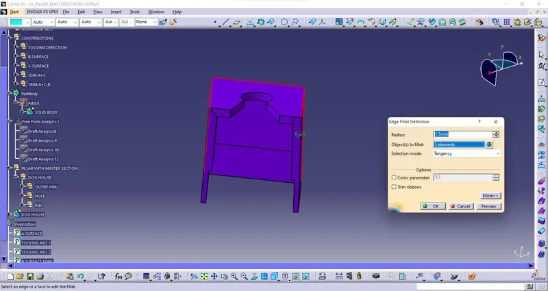
EDGE FILLETS:-
LOWER SECTION OF THE DOGHOUSE:-
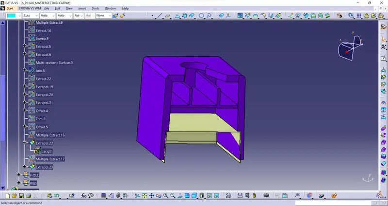
- Now we need to give the bottom cutout for the dog house. To give the bottom cutout, I extracted the surface and offset it to 1mm outside (the bottom cutout should be 40% of the thickness of the dog house). I extract the upper surface of the dog house and offset it to 17mm bottom direction, to trim with the offset of the inner surface.
- After trimming the bottom cutout surface, I split the surface from the solid shell of the dog house.
RIB:-
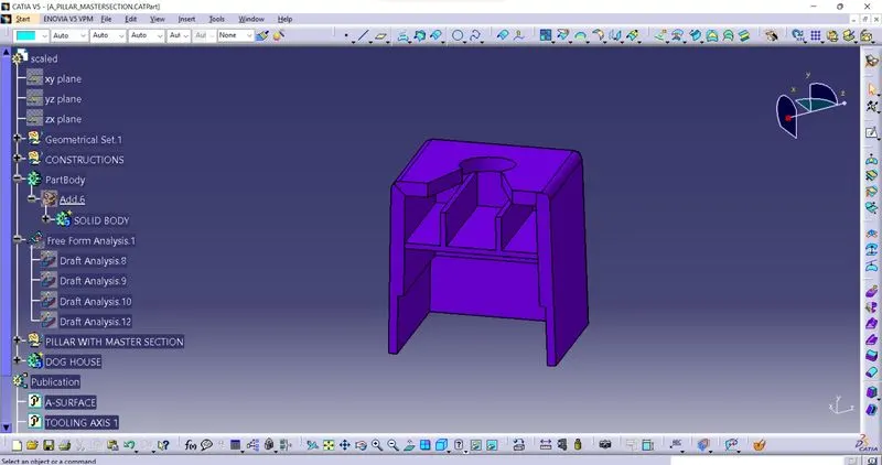
Then create the rib inside the doghouse with same approch extract the line and sweep the extrected line and fill the open surface and apply closed body command in part and then add with the doghouse.
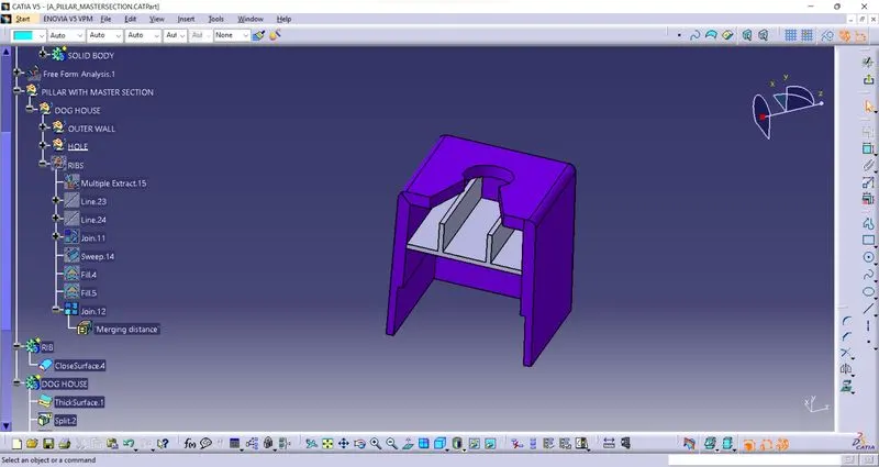
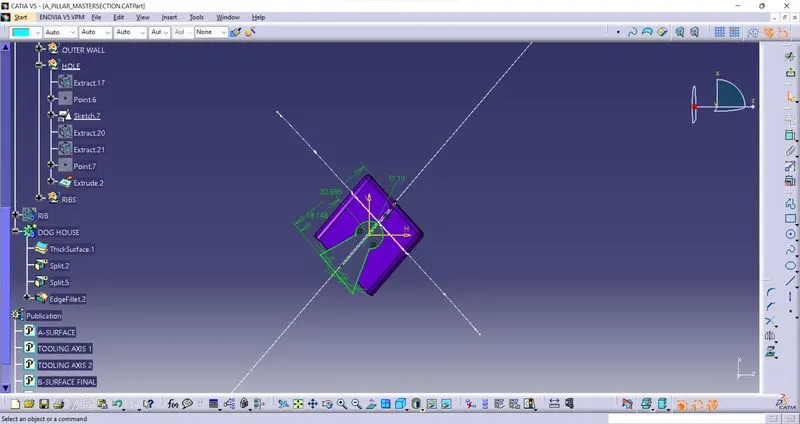
- I created a sketch for the top cutout on the dog house, and I pad the sketch to the downside and removed it from the dog house part body.
Dog house top cutout sketch:-
FINAL DOGHOUSE:-
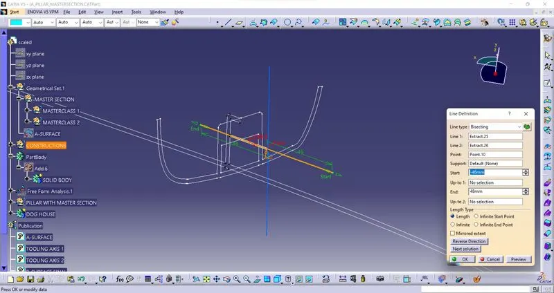
NOW I HAVE TO CREATE TOOLING AXIS FOR DOGHOUSE SO I USED BISECTING METHOD WITH THE HELP OF MASTER SECTION.
DRAFT ANALYSIS:-
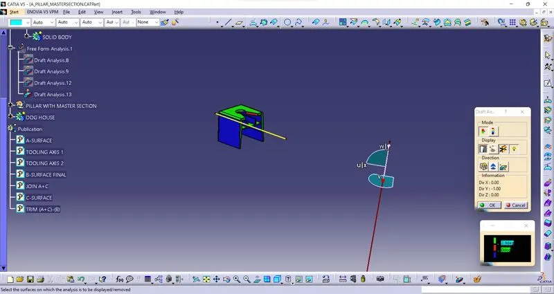
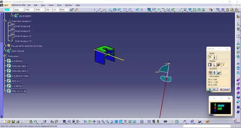
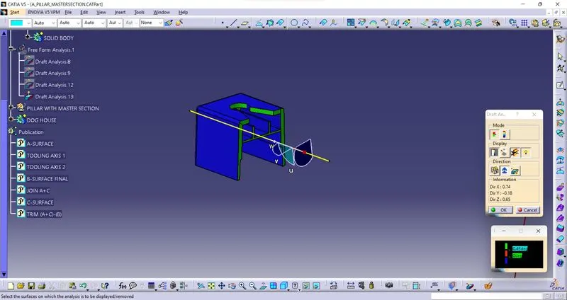
AND FINALY I TRIM THE DOGHOUSE WITH MAIN SURFACE:-
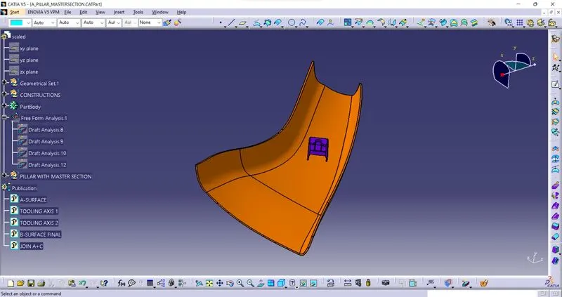
AGAIN DRAFT ANLAYSIS AT ANGLE 2.9 AND 0.45:-
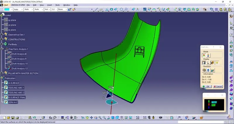
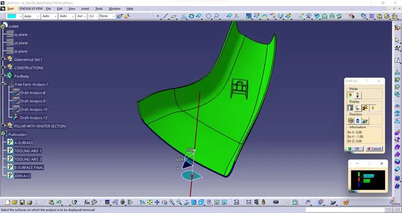
ERRORS:-
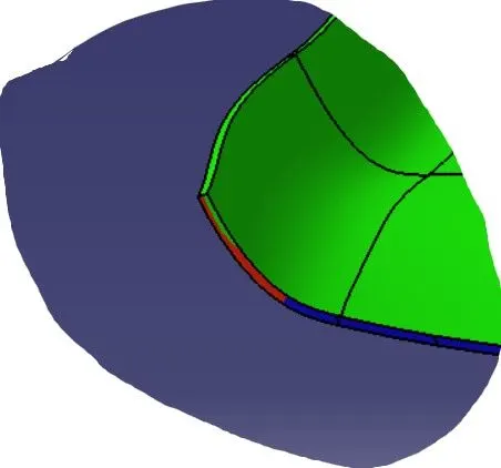
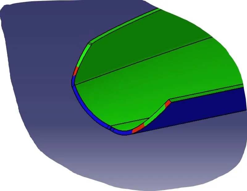
NOTE:-This is happening because of A-surface at this position A-surface are tiltted thats why i found an error.
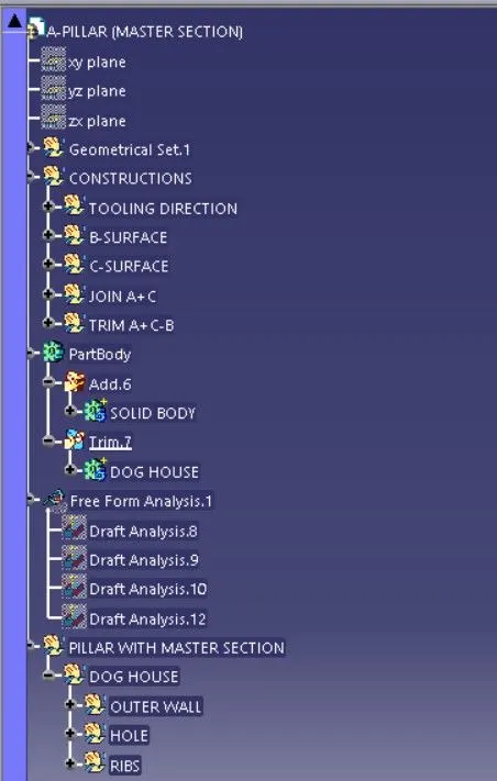
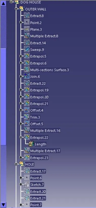
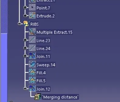
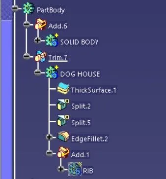
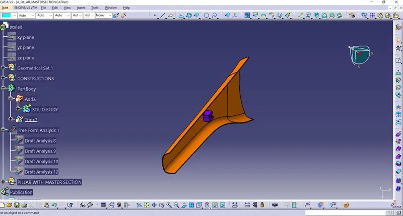
GEOMETRICAL TREE STRUCTURE:-
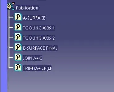
PUBLICATIONS:-
VIEWS:-
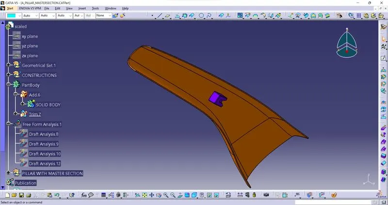
ISOMETRIC VIEW:-
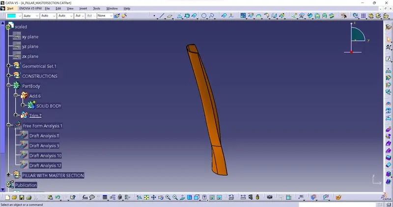
FRONT VIEW:-
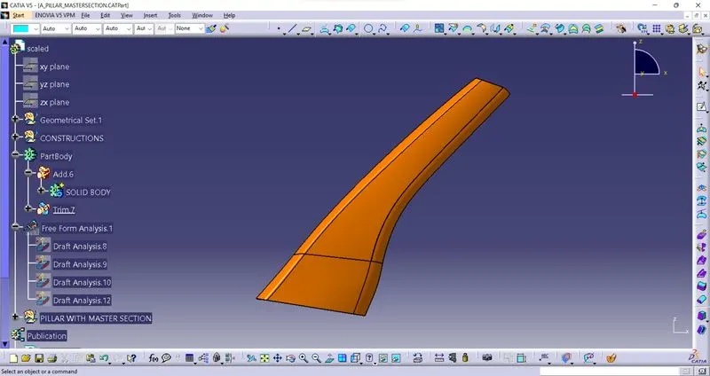
SIDE VIEW:-
TOP VIEW:-
ALL VIEW IN ONE FRAME:-