Week 9 - Project - A pillar Design with Master Section
Answer:
Report on draft analysis of given class A surface and solid model with enginnering features attacting to it.
Aim: To create solid model from given class A surface then attaching the engineering features to it following the master section.
Given Class A surface:
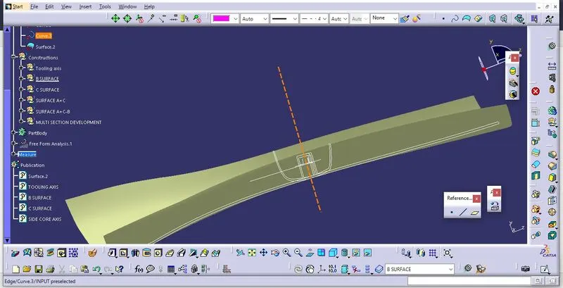
Step 1: Check the connectivity of A surface by Boundary command, modify the pathes if there are any in the surface.
Step 2: Create tooling axis for the draft analysis
Finding the tooling axis of the component. The tooling axis is nothing but the mould opens or cavity opens. Check the best possible tooling axis.
First create the dummy tooling axis, by creating a line passing through the middle point of master section and normal to the surface
Creating the tooling axis by bisecting method: Pick two points on each side of the wall in the master section, create line through each one of them, now create the bisecting line between them, the resulting axis is our main tooling axis.
Now perform the draft analysis through the draft analysis toolbar in the bottom. after opening the draft analysis toolbar drag the compass on the tooling axis, click on the lock symbol after compass is aligned.
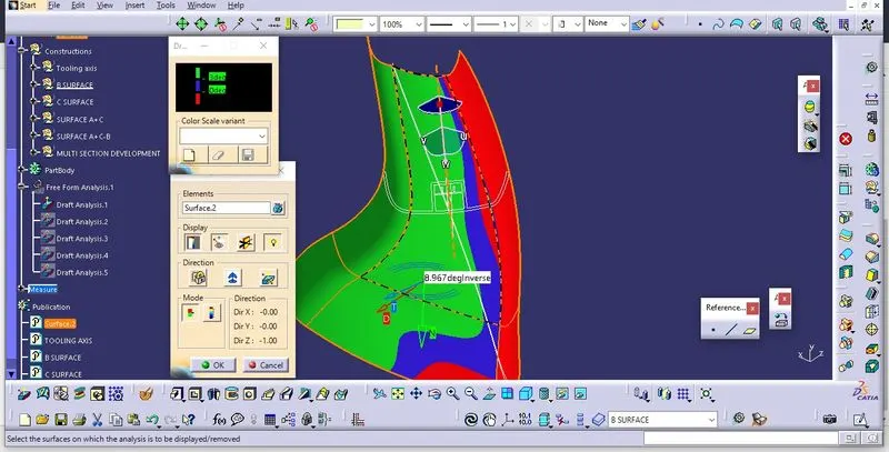
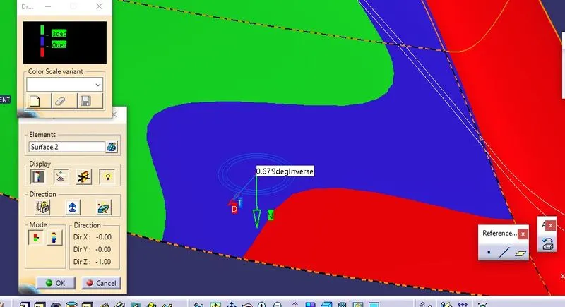
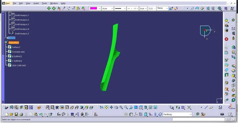
Blue area in the A surface shows that we should report to A surface development team about the improvment on the surface are needed as it has minimum draft angle of 0.679 deg which is so less , green area is clearing the draft.
Step 3: Creation of Class B and Class C surface
Class B is created by Offseting the class A surface to 2.5 mm inside direction, then seprately modifying the missing patch by sweep command with guide curve, finally join the surfaces to create B surface as shown.
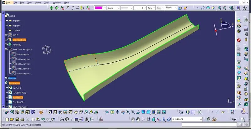
Now, create Class C surface by first creating the boundaries on A surface then using the sweep command with reference surface as A surface to create C surface, extrapolating the surfaces around the gap to fill it and form a close surface as shown below.
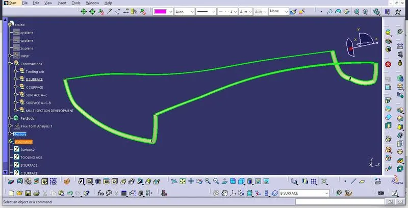
Step 4: Create the solid model out of the close surface combining all three surfaces
First join A surface with C surface then finally Trim them with B surface to create the close surface. And use close surface command in the part workbench to create solid model out of it.
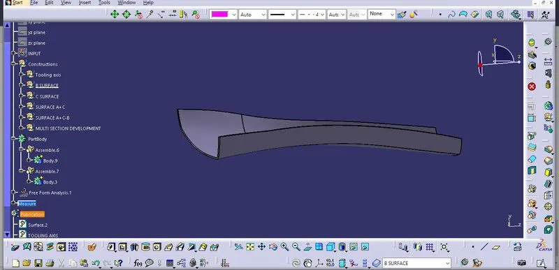
Step 5: Now start developing the engineering features following the dimensions of master section.
So we found there is dog house, ribs inside it and one pin hole at the top surface.
so create doghouse by padding the sketched line in the mastersection , closing the back side of dog houseby surface thickening, then develop the core part by design rules as shown. Create Ribs by simply padding and apply union trim with the dog house surface, and pin hole is created by pocket command on the top surface of dog house.
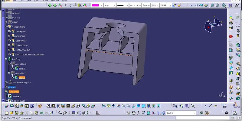
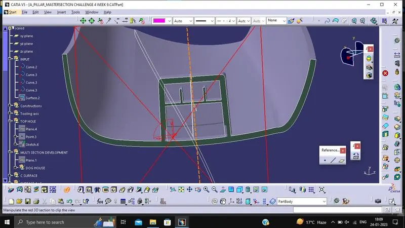
draft analysis on the dog house need to be done after its creation as shown
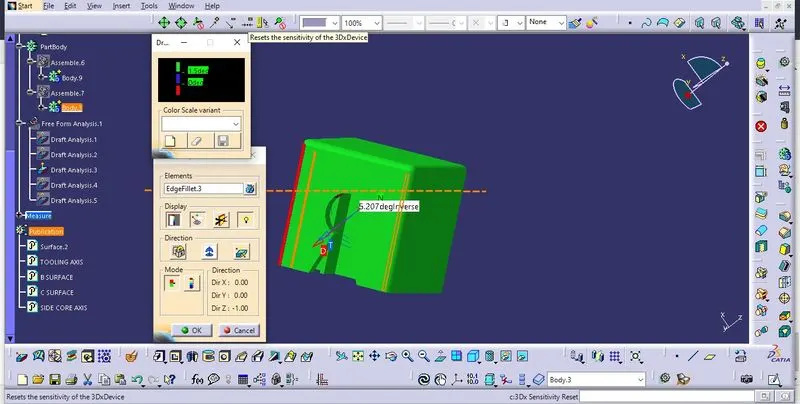
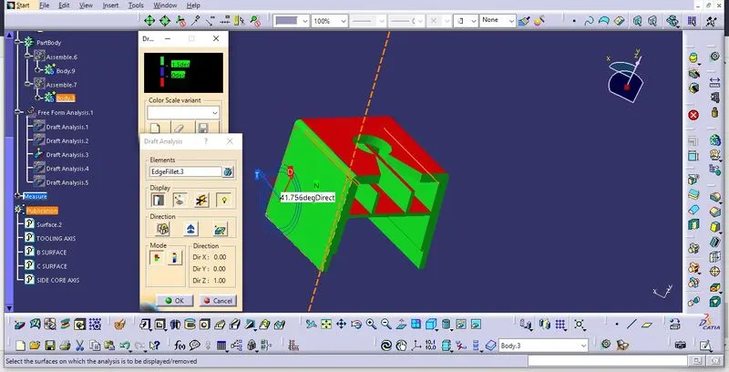
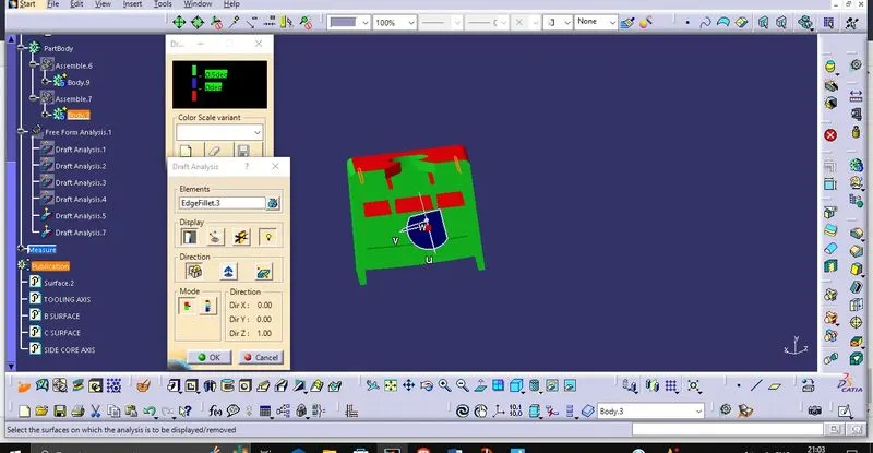
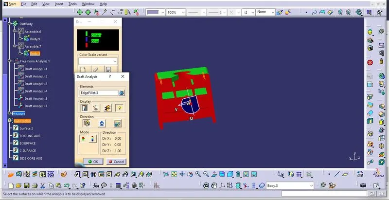
by reversing the draft analyis direction we get our clear draft, so our deisgn is proper.
now perform the draft anlysis on final surface as shown.
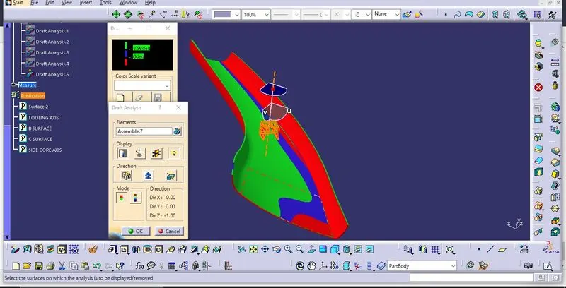
All blue area in the draft analysis is due to deformity in our class A surface, so that should be improved by class a development team.
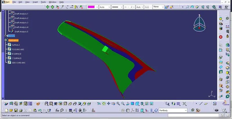
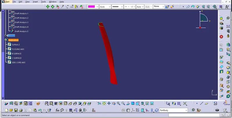
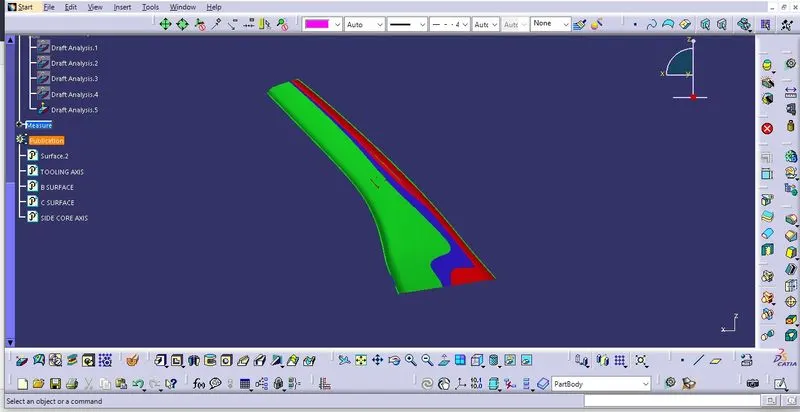
So our final model is complete.