Week 9 - Project - A pillar Design with Master Section
PILLAR MASTER SECTION
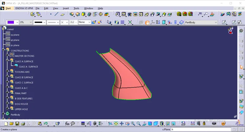
Creation of tooling axis
for the creation of tooling axis we need to see the class A surface in all the views (front view, top view, side view)
by using the master sections and also using the line bisecting method we can easily create the tooling axis
after creation of the tooling axis we need to do the draft analysis on the class A surface that they are provied as shown in the below figure.
Draft analysis on the class A surface
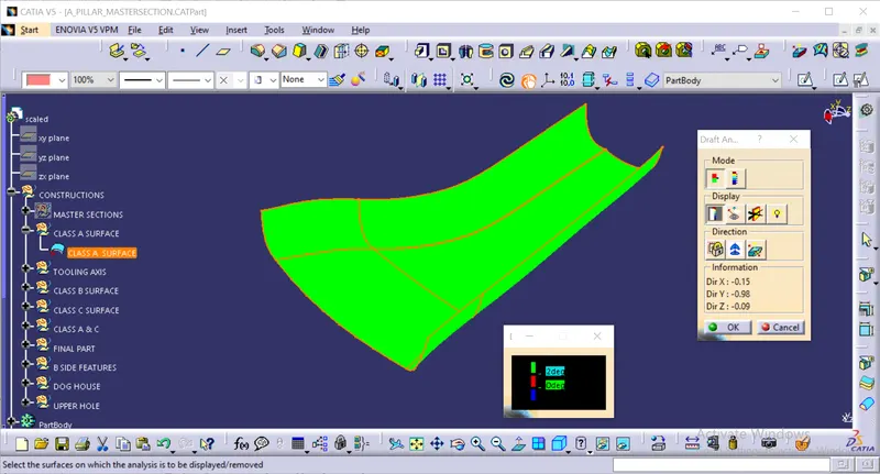
draft analysis on the class A surface as shown in the above figure for that we need to open the draft analysis then we need to select the class a surface after that we need to make it into material mode after that we need to place the axis system on the tooling axis then lock the movement of the axis system after that need to click on the class A surface then the surface colour changes as per the criteria as shown in the above figure.
after completion of draft analysis all thefaces of the given pillar class A surface is clearing the 2 degree draft angle from the above figure.
Class A surface
above figure shows that the class A surface
Class B surface
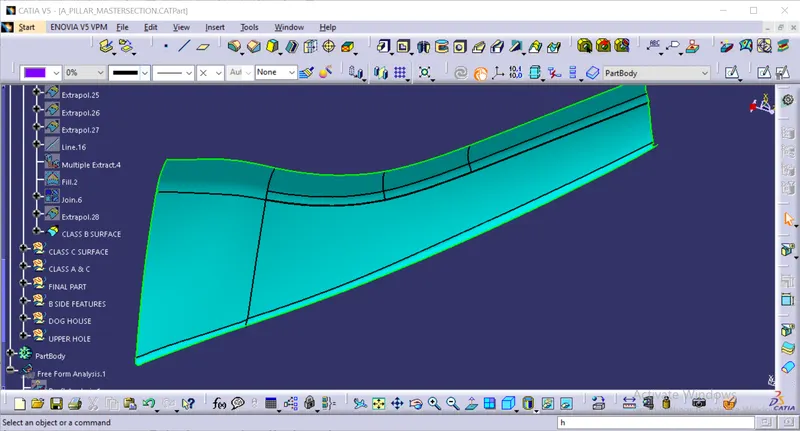
the above figure shows that the class B surface this surface is created by using the bisecting method.
Class C surface
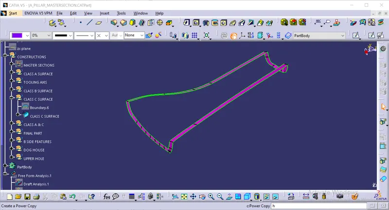
the above figure shows that the class C surface this surface is created by using the sweep with the reference surface with angle of 90 degrees .
Class A & C
the above figure shows that the combination of class A surface with class C surface by using the join command with high precision value of 0.001.
final part
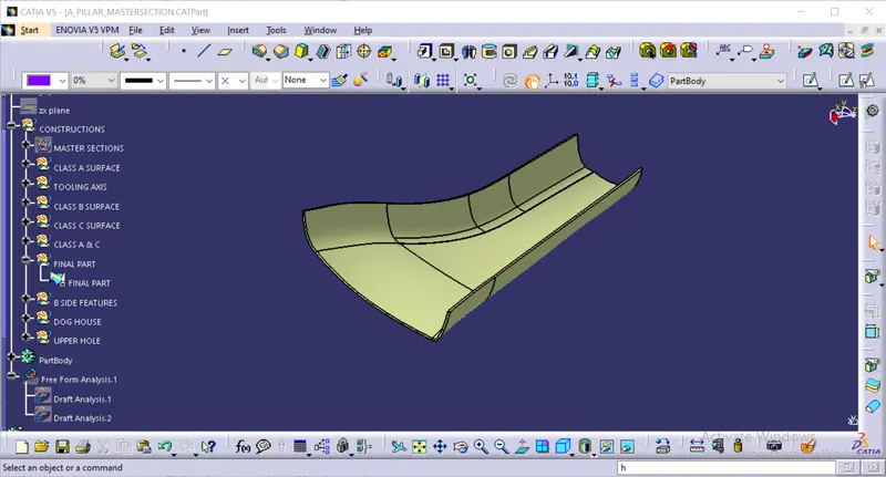
the final part as shown in the above figure the part is created by trim the class b surface with class A and C surface .
after completion of the final part we need to create the close surface
before the close surface command we need to ensure that the created part doesnt contains any open boundaries by using the boundary command as shown in the below figure
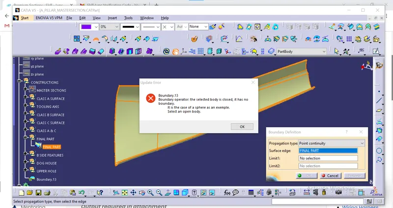
after ensuring that the created part doesnt contains any open boundaries then we need to go to the part design then we need to click on the close surface command as shown in the below figure.
Close surface
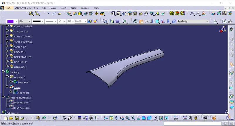
after that we need to define the part body after that we need to go to the part design after that we need to go to the close surface command after that we need to select the final part that we have created then we need to click on ok it forms the close surface.
creation of the B side features
for the creatio of the master section we need to follow the given master sections and also the design rules
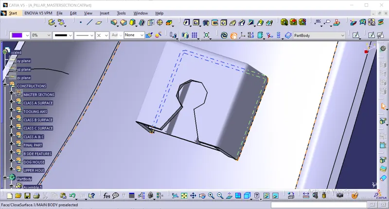
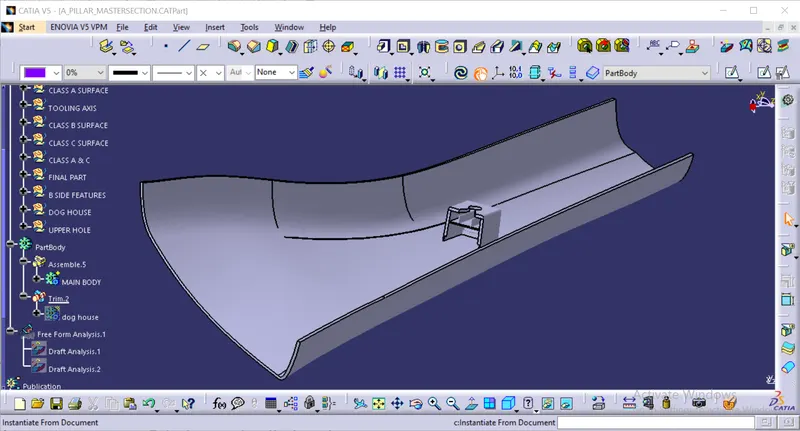
after completion of the master section we need to do the draft analysis on the part that we have created
Draft analysis on the final part
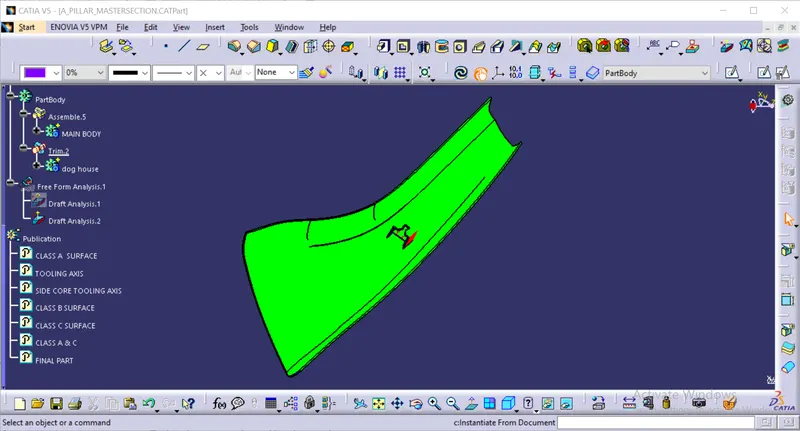
before completion of close surface command we ned to calculate the draft angle on the final part that we have produced for that we need to go to the insert tab after that we need to go to the analysis tab on that there is a option called draft analysis we need to selest the draft analysis after that there is a small window is opened as shown in the above figure. after that there is a option which is called as axis system we need to select the axis system after that we need to select the axis system and drag it and place it on the tooling axis that we have created by using the red dot which is resent i the axis system after that we need to click on the lock button for locking the movement of the axis system after that we need to go to the material mode after that we need to click on the final part. after that the colour of the part is changed as shown in the above figure .it shows the colour wee need to check the draft angle as shown in the criteria. as shown in the above figure after that we need to click on the option as shown in the above figure.
we need to do the draft analysis before the close surface command we need to do close surface after completion of draft analysis. we need to define the part body after that we need to go to the part design after that we need to use the close surface command before using the close surface command we need to make sure that the body we have create is complletely closed by using boundary command after that we need to move on to the close surface command after clicking on the close surface we need to the select the body that we have created after that just we need to click on the ok after that the close surface is created sucessfully .
tree structure
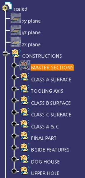
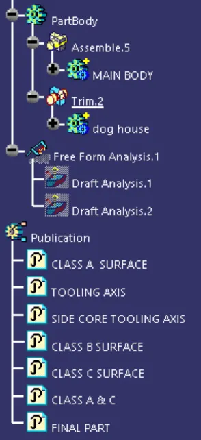
we need to maintain proper tree structure because proper tree structure gives us the proper understanding of the project to others who are gonna working on the same project.