Week 8 - Challenge 2 - Switch Bezel Design
Switch bezel
creation of the tooling axis
for the creation of the tooling axis frst we need to check all the view of the given class A surface ,for which view clears the maximum flat surfaces
front view
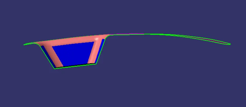
side view
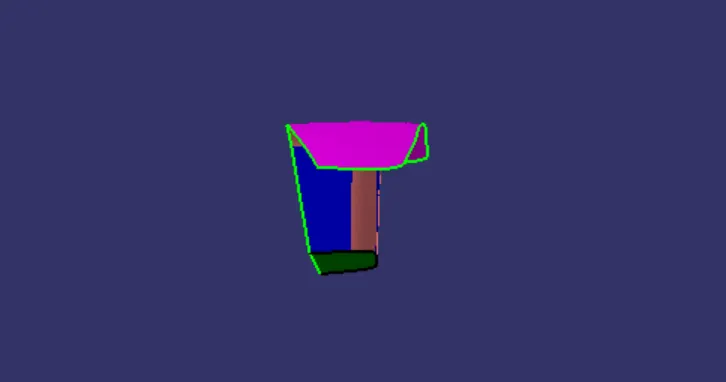
top view
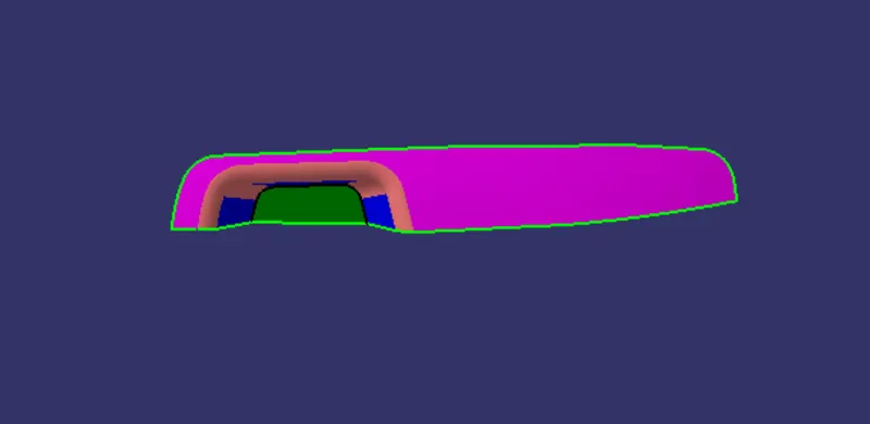
As shown in the above pictures (front,side, top views)
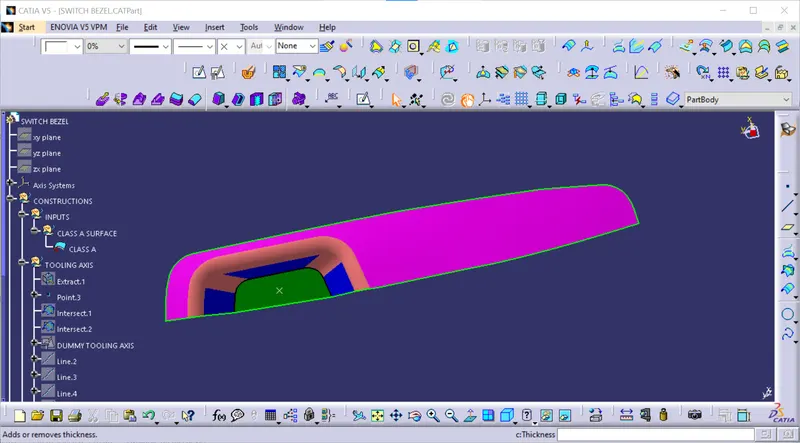
first we need to create a point on the center of the base as shown in the above figure
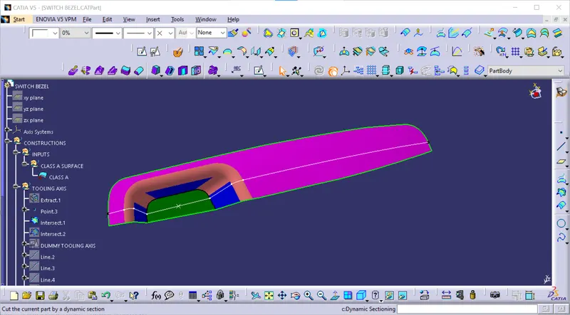
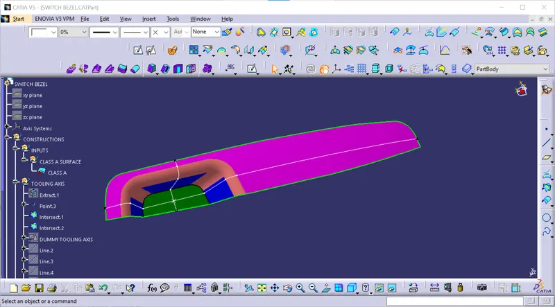
after that we need to use intersect command with respect to the axis system and the given point in both x and y directions as shown in the above figures
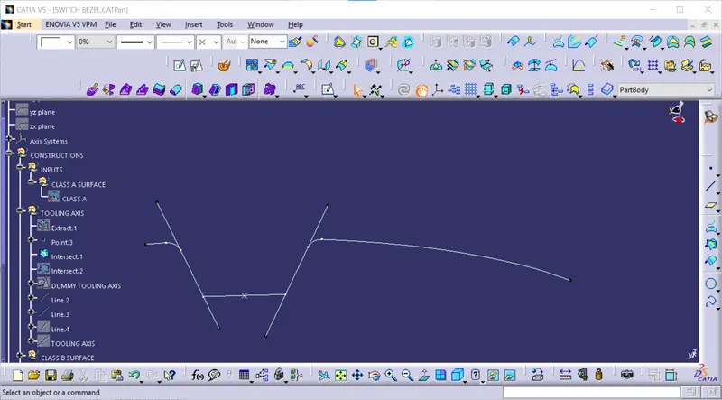
after that need to create the lines with respect to the intersect that we created as shown in the figure.After that create a bisecting line with respect to the lines that we are created then it forms a tooling axis
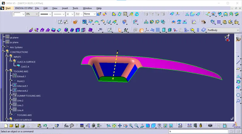
after bisecting the lines then it forms a tooling axis as shown in the above figure
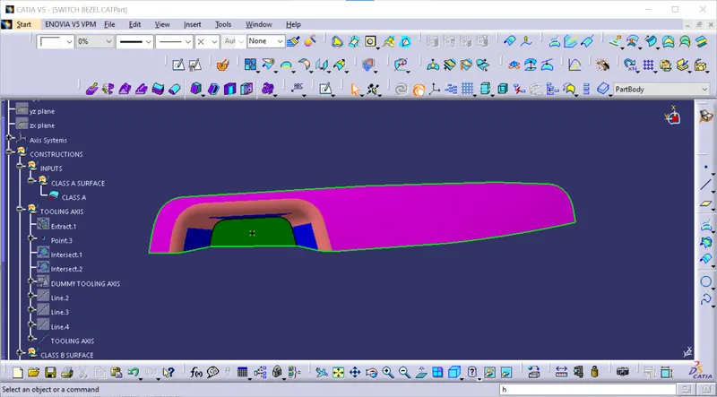
after creating the tooling axis need to make sure that the tooling axis is clearing all the flat surfaces as shown in the above figure.
Draft analysis of a class A surface
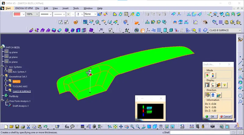
as shown in the above figure draft analysis done on the class A surface hence the draft anglee is which is shown as 3 degree for checking the draft analysis we need to go to the analysis tab after that need to open the draft analysis command for performing the draft analysis . for that after opening the draft analysis commmand then need to click on the axis system option in that particular draft analysis window. after clicking on the axis system then need to drag the axis and put it on the tooling axis after placing the axis system properly then need to lock that axis sytem by clicking on the lock option in the draft analysis then we need to click class a surface once then we will get the required output as shown in given figure
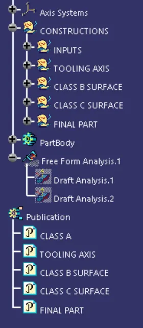
Tree structure
Class A surface
Class B surface
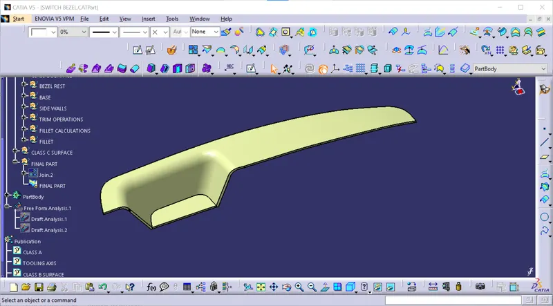
Class c surface
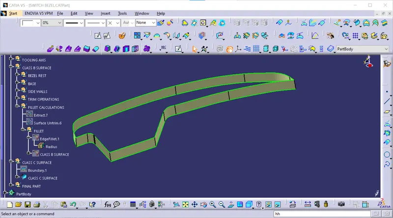
class A and C combined surface
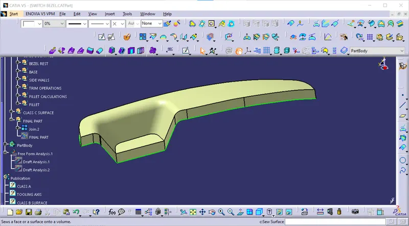
after joining the class A and class C surface by using trim command then the above surface is formed
final part
after joining tha class A and c surface with the class b surface to form the final part as shown in tha above figure
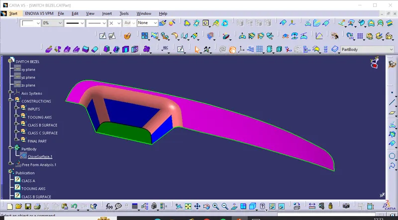
close surface part
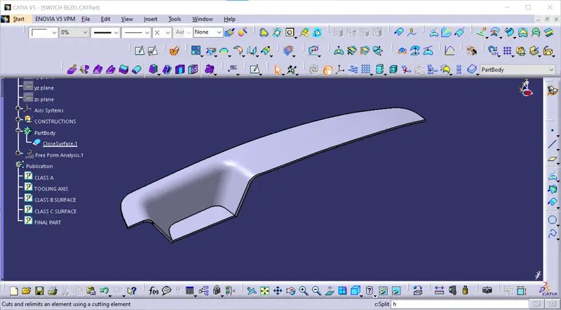
for the close surface command we need to consider the partbody first after that need to click on the close surface command. then need to click on the surface that after combining the class A ,B and c surafce then click on the ok option then the close surface is applied for the partbody
final draft analysis
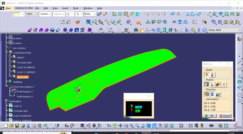
after complletion of joining the class A ,B and C surfaces then we need to do the draft analysis with the final part as show in the figure .this draft analysis is done to find out the proper draft angle .if there is no proper draft is there then the friction between the part and the core increases then parts may be damaged for avoiding these problems we need to consider the draft . for checking the draft angle for that we need to do the draft analysis on the final part that we are designed.
for the draft analysis first need too open the analysis tab which is present in the insert tab on that analysis tab we need to open the draft analysis command after opening the draft analysis command a window is opened as shown in the above figure on that window ther is an option called axis system .click on the axis system option an axis system occurs on the catia screen just need to drag that axis system by holding the red dot on the axis system with the mouse right button . then need to drag that axis system and place it properly in the tooling axis that we are created as shown in the above figure make sure that the axis system placed properly the w axis should placed along the tooling axis properly .After placing the axis system then we need to lock the movement of the axis system that we are placed in the tooling axis .there is an option called lock need to click on the lock button to avoid the free movement or unnecessary movements of the axis system during the draft analysis
After locking the movements of the axis system then we need to click on the surface of the part then the part is chaging the colour into green as shown in the figure that shows that the raft angle of the part is under 3 degree . there are some more options are there in the draft analysis command .Those options are used for different purposes in the draft analysis
Also it consists the mode , display and diection in the mode command it shows the draft angle with respect to the colour in that display option there are some more options are there whiich is used for the different purposes after that there is a information option is there in the draft analysis option it shows the directioon information inn x,y ad z