Week 8 - Challenge 3 - Coin Holder Design
COIN HOLDER
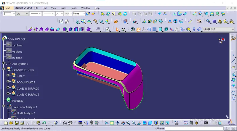
Creation of tooling axis
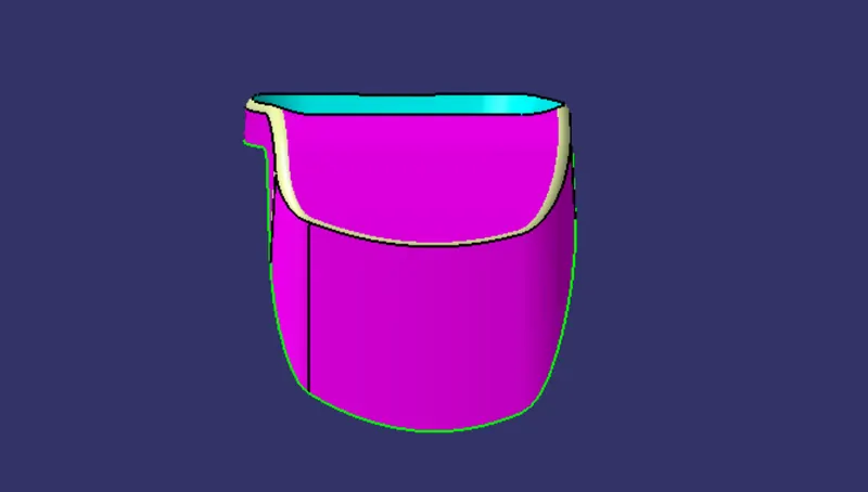
for the creation of the tooling axis frst we need to check all the view of the given class A surface ,for which view clears the maximum flat surfaces
front view
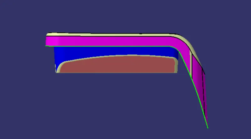
side view
top view
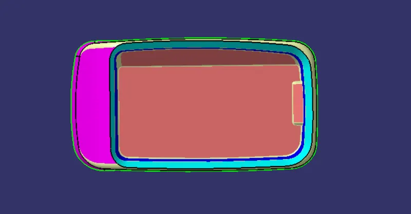
after checking all the views (front view,side view, top view) in the top view it clears all the flat faces hence we need to create tooling axis in top view
after that we need to extract the base of the part as shown in the below figure with respect to that we need to make a point with respect to the center of that particular extract
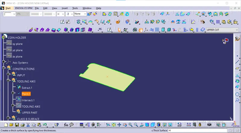
after extract then we nned to place an axis system in that particular point that we have created and we need to make an intersect with respect to the class a surface and the axis system that we are created as shown in the below figure
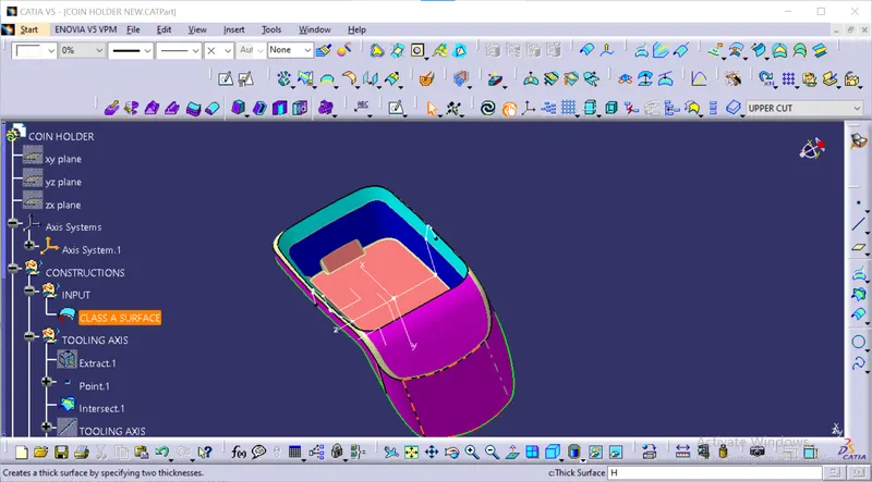
after that we need to check that intersct properly for that we can hide the unnecessary elements
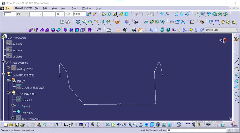
after making an intersect we need to check the intersect clearly. from the above figure the walls of the intersect are 90 degree angle with base for that we need to make a tooling axis normal to the base
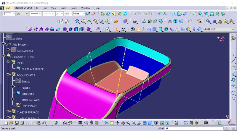
As shown in the above figure the tooling axis is sucessfully created.
Draft analysis on class A surface
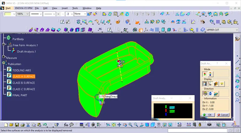
The above figure shows that the draft analysis done on the coin holder class A surface which is used to know the draft angle of the class A surface . from the above draft analysis, the draft angle of the class A surface is 3 degree as shown in the above figure
class A surface
class B surface
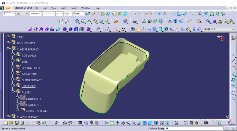
the above figure shows that the class B surface which is generated with respect to the class a surface by using various commands
class C surface
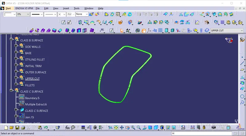
the above figure shows that the class c surface .this is made by using the sweep command by using e sweep command in that sweep command we cannot produce the class c surface by using with respect to the tooling axis option for the parts like this . we can use the sweep with respect to the reference element we can do the sweep command option with an angle of 90 degrees it is produced as shown in the figure
class A and C
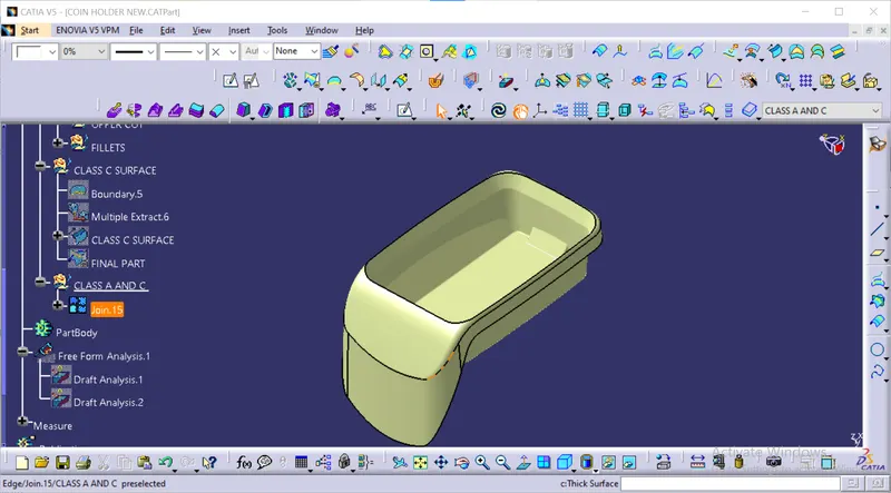
the above figure shows that the the combination of class A and class C surface
class A,B and C
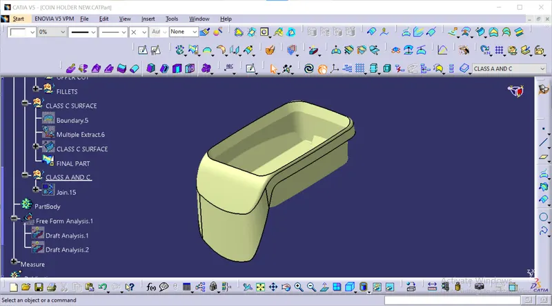
after joining the class a and c surface by using join command then we need to use the trim command for joining the class b surface with the class A and C surface . after using the trim commmand then we get the combined part of class A,B & C. as shown in the above figure.
Draft analysis
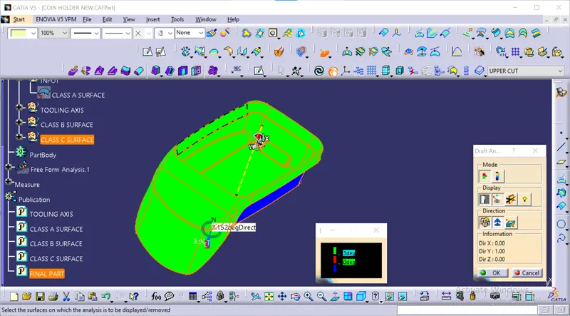
after completion of the design then we need to check the draft angle of the part that we are designed for that we need to go to the insert tab in that insert tab there is an option called analysis . we need to select that analysis tab in that analysis tab there is an option called draft analysis , we need to select that command in that command there is a subwindow opens in the catia as shows in the above figure we ned to click on the axis system option which is present underdirection option after selecting that axis system we nned to place the mouse curser in the red dot which is present in the axis system. after that we need to drag that axis system then place it on the tooling axis after placing on the tooling axis we need to check once weather the axs syste is pllaced properly in the tooling axis after checking that we need to top the movement of the axis system from the tooling axis for that there is a option called lock . after clicking on the lock command the movement of the axis system is locked on the tooling axis . after locking the axis system then we need to click on the part once then the colour of te part is changed according to the draft angle which is shown in the seperate window . from the above part the minimum draft angle is ensured that is 3 degrees s shown in the above figure this draft analysis is very important for knowing of the draft angle of the partthat we are designed .
after checking of the draft analysis then right click on the part body then define it as working element them go to the part design .after that need to clickon the close surface command .before going to the close surface command we need to ensure that part does not contains any open boundaaries by using boundary command as shown in the below figure
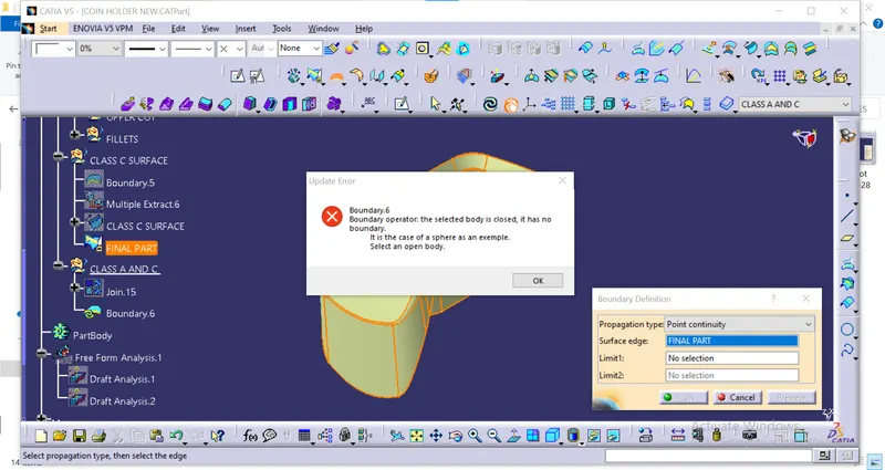
after conforming that the part that we are produced does not contains any open boundary then we can proceed to the part design and after that click on the close boundary then we need to click on the part that we are produced then the close surface is formed as shown in the below figure
Close surface part
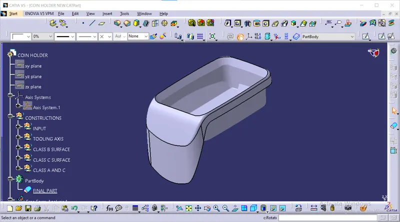
final part which is created by using close surface command as shown in the above figure