A pillar Design with Master Section
Title-
A pillar Design with Master Section
Introduction-
An A-pillar structure on an automotive vehicle is manufactured from a formed tubular member that replaces the conventional inner and inner reinforcement members. The door opening panel is formed with  conventional flanges that are welded or adhered to the tubular member to provide a conventional uniform surface against which the windshield and front door seals can be supported. The door opening panel flanges can be welded by one-sided welding techniques, such as laser stitch welding, to the tubular member. As an option, the movement of the front door seal from the ab flange to the front door can provide an opportunity to form the tubular member with a still larger cross-section for enhanced strength. The distance dimension spanning the opposing flanges to define the standard arc for maintaining binocular vision is retained while increasing the strength of the A-pillar due to the enlarged cross-sectional configuration provided by the tubular member.
Given data
- Class A surface- Class ‘A’ surfaces are primarily used in the automotive environment and refer to those surfaces which are visible in a product. In other words: A - class surfaces are those aesthetic/free-form surfaces, which are visible to us (interior/exterior), and have an optimal aesthetic shape and high surface quality.
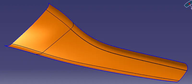
- Master sections- Master Sections are the guides for design requirements which shapes the component after technical styling of Class A Surfaces.
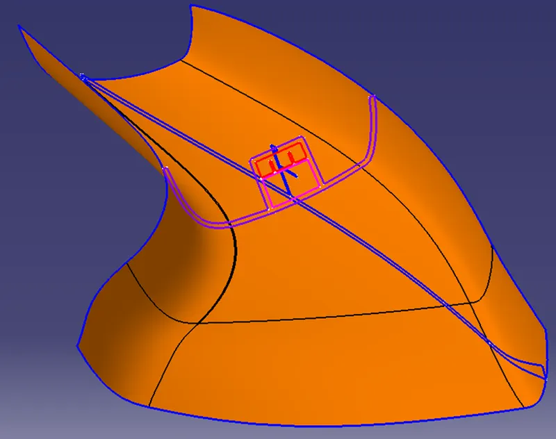
Procedure
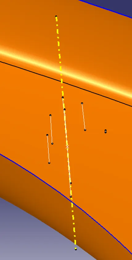
- Tooling axis- - Tooling axis is nothing but the direction in which the core and cavity opens and closes. Design engineer works is to analyse the Class A surface and find out the best possible tooling direction keeping in mind all the draft angle is with respect to the tooling axis so that the component can be easily ejected from the moulds.
Here we are going to create the tooling axis through the bisecting method. In this method we are going to extract 4 lines from the master section. Then after we created the two bisecting lines from the 4 extracted lines. After that we have created another bisecting line from 2 bisecting lines, which is our Tooling axis.
- Class B surface-
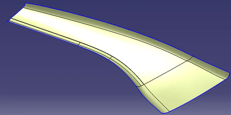
- Class C surface-
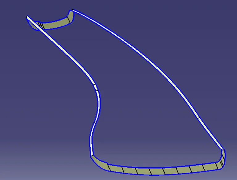
- Final surface-
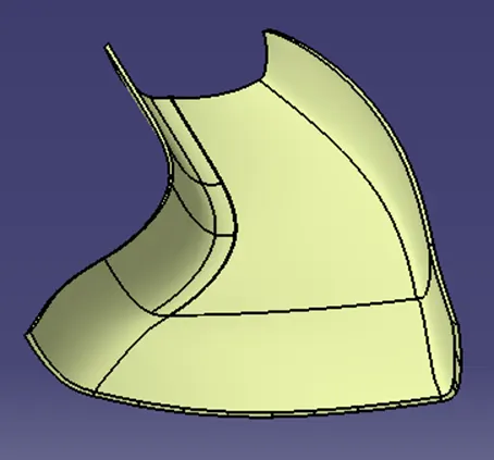
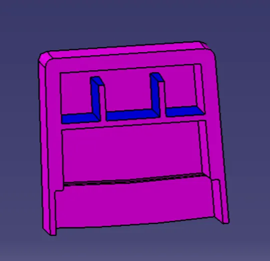
- Dog House-
Using the Master Section the Doghouse is created and then part modelled using Thickness option
- The 4 Way Locator is Formed above the Dog House which locates the B pillar towards the Mating Surfaces
- The Dog House Design Rules are
- The Thickness of the Connecting surface towards B Side should be 40% off the main thickness
- The Walls are drafted with Min 0.5 Degrees along the Main Tooling Direction
- The Attachement feature created needs a seperate tooling axis to clear the part Hence a Lifter Axis is used
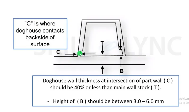
- The Surfaces that are cleared along the Lifter axis are also given a Minumal Draft
- The Height of the attahcment walls should be a minimum of 3 mm
- This avoids the plastic defects on the B Side and maintains the texture of A Side
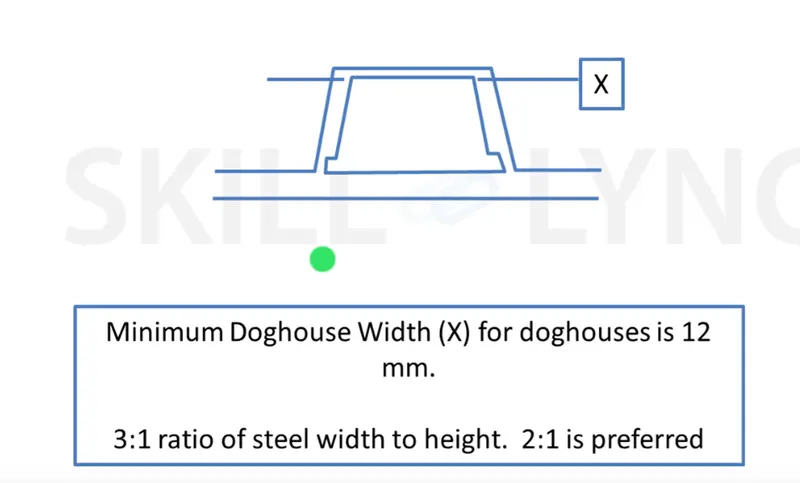
Sketch-
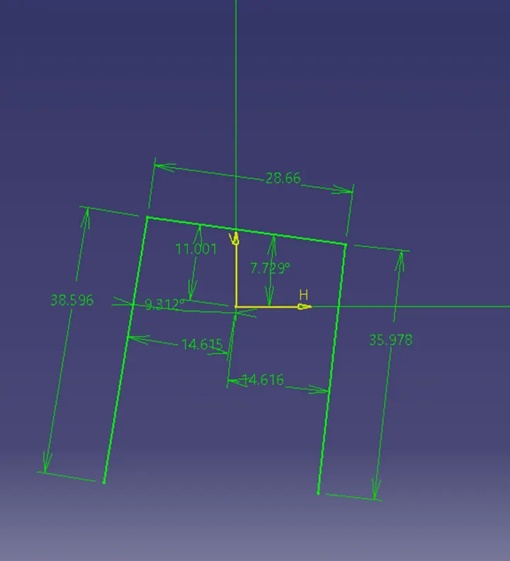
Thick Surface-
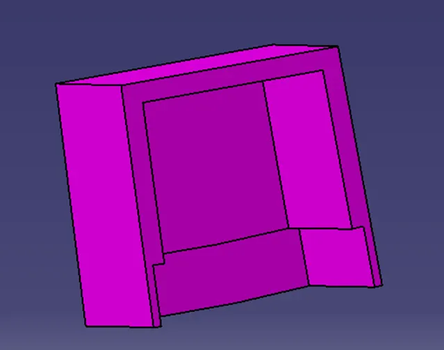
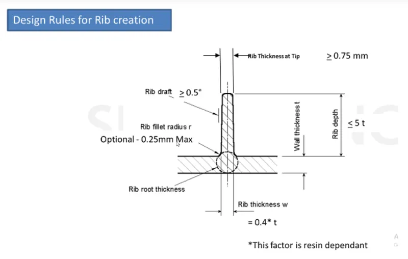
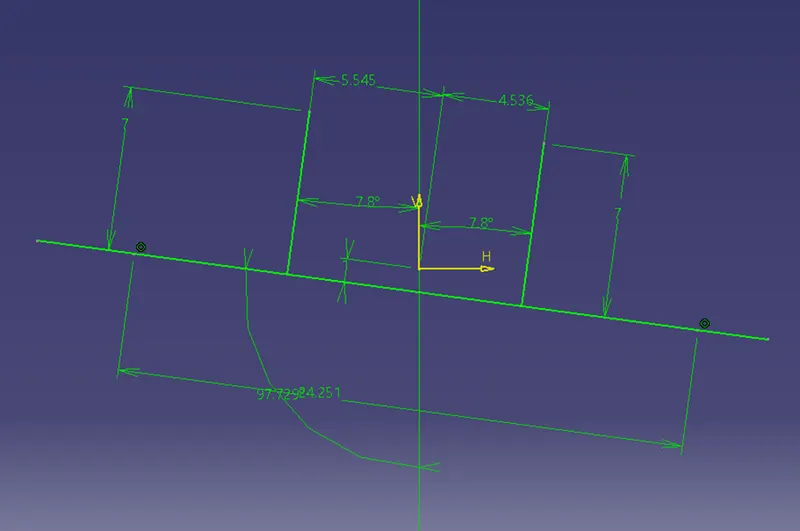
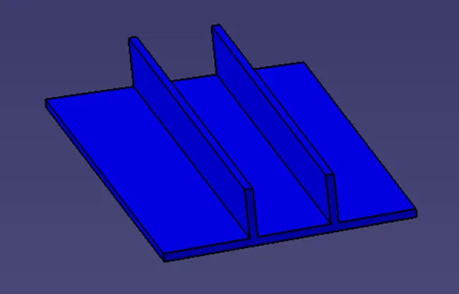
- Ribs- Ribs provide stifness to the parts and can be to impart toughness without increasing the part thickness and are locators and provide allignment to the mating parts
- The Design Rules for two way and four way fixtures are
- Rib Wall Thickness should be 0.4 times of Thickness of the part
- The Drafted walls of rib should be within 0.5 degrees
- The top height of rib should be at least 70 mm thick to allow the molten plastic to reach the top to avoid Short Shot
- The Thickness of the Rib, Fillet Radius, Draft and rib root thickness are measured and are withing the design specifications
Ribs sketch-
Ribs Thick surface-
Final dog house with ribs-
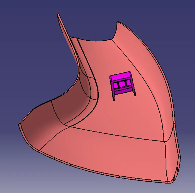
Final Pillar design-
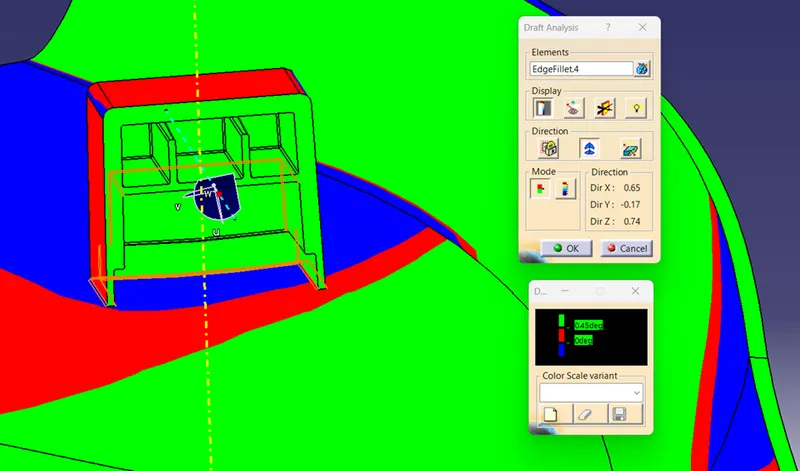
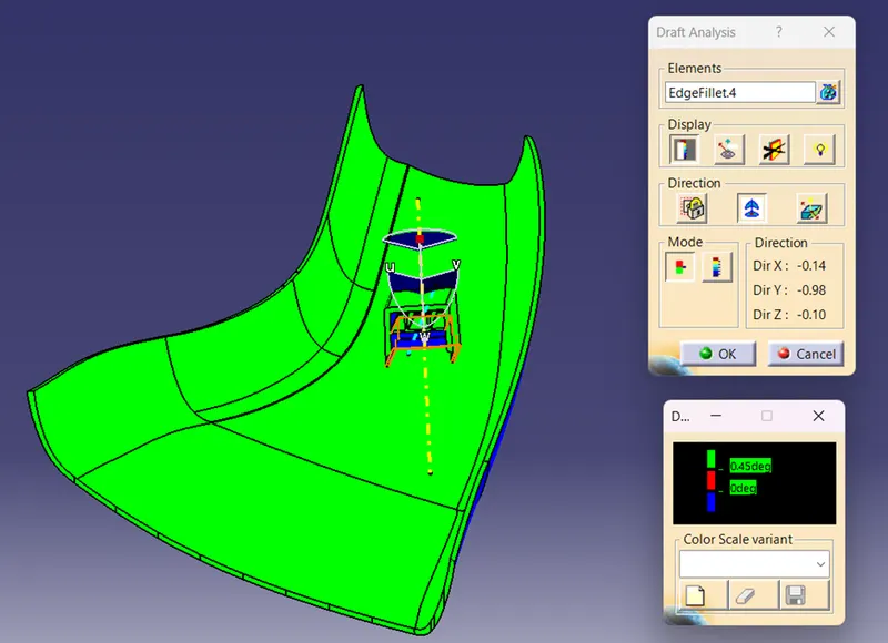
- Draft analysis- - The draft analysis button within CATIA V5 will helps us quickly gather the draft angle on multiple surfaces without the need for tedious manual measurements. Here is a quick rundown of how the icon works when you have a given die direction.
to check whether our tooling axis is proper or not we do the draft analysis.
- Go to insert > analysis > feature draft analysis.
- Align the compass with the tooling axis.
- Then, click on the Class-A surface to see if the it is within the permissible limit of the draft values.
- The Class-A surface should turn green and then draft value should be given as 0.45 degrees.
- Draft analysis of pillar with tooling axis-
- Draft analysis of Inside area of dog house and Ribs with lifter axis-