Week 9 - Project - A pillar Design with Master Section
DIFFRENT VIEWS OF THE FINAL PART
ISOMETRIC VIEW
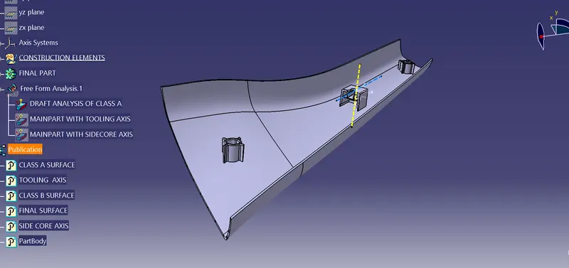
TOP VIEW
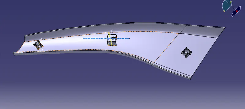
SIDE VIEW
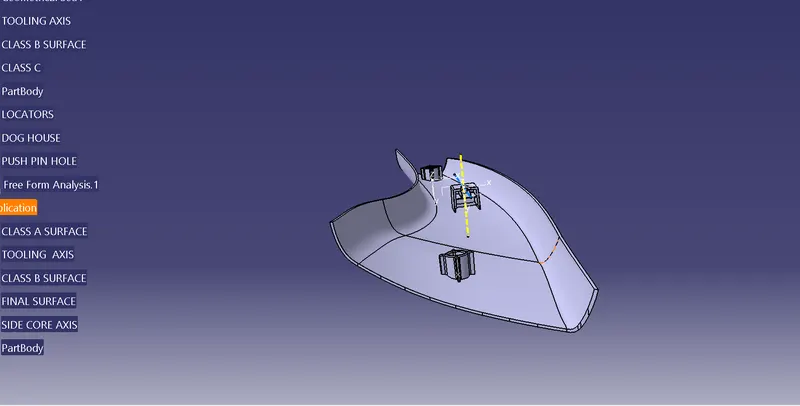
DRAFT ANALYSIS OF CLASS A SURFACE
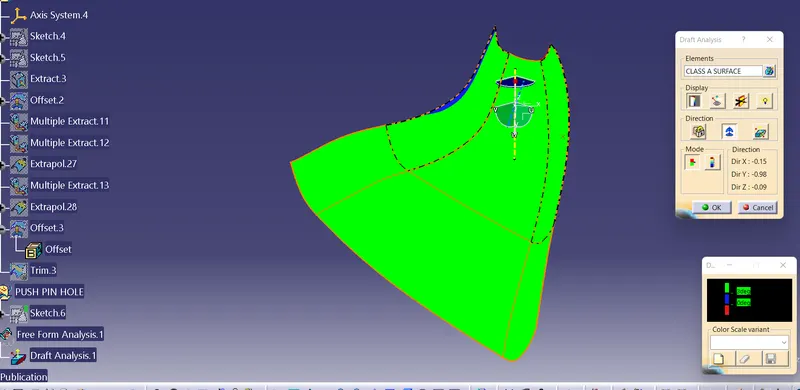
If the draft analyis is showing green the part is having required draft angle and is ready to work on.
DRAFT ANALYSIS OF FINAL PART WITH RESPECT TO MAIN TOOLING AXIS
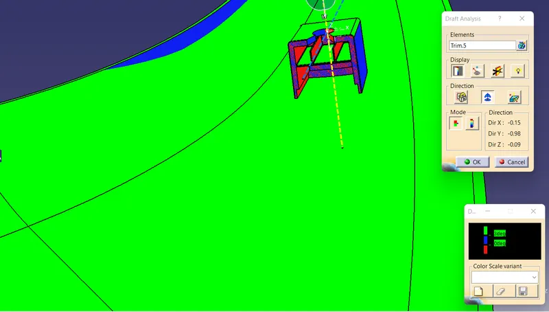
In this draft analysis is done with respect to the main tooling axis and the part showing blue is having 0.5 degree draft angle and interior part is having negative angle draft.
DRAFT ANALYSIS OF FINAL PART WITH RESPECT TO SIDE CORE AXIS
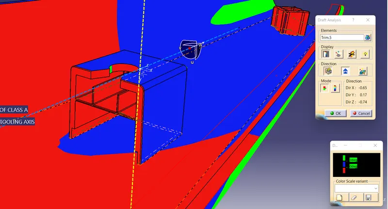
Here the outside part is having 0.5 degree draft and interior areas is having negative 0.5 degree draft.
REPORT
DRAFT ANALYSIS-
Draft analysis is used to check whether suitable draft angle is given to the component, here we can see the green area of the component is having an angle greater than 1.45 degree and area in red shows there is low draft angle.
TOOLING AXIS
Tooling axis Creation Draft Analysis on Class A Surface
The main objective is to create Draft Analysis by Providing the Tooling direction of a class A surface
- The draft analysis command enables you to identify whether the component you drafted will be easily removed or not.
- After performing draft analysis we can able to recognize the material wih draft according to the colours allotted.
- Tooling direction defines you, that in which direction that the component is being removed and the tooling direction was the main consideration for both plastic parts andd mould parts.
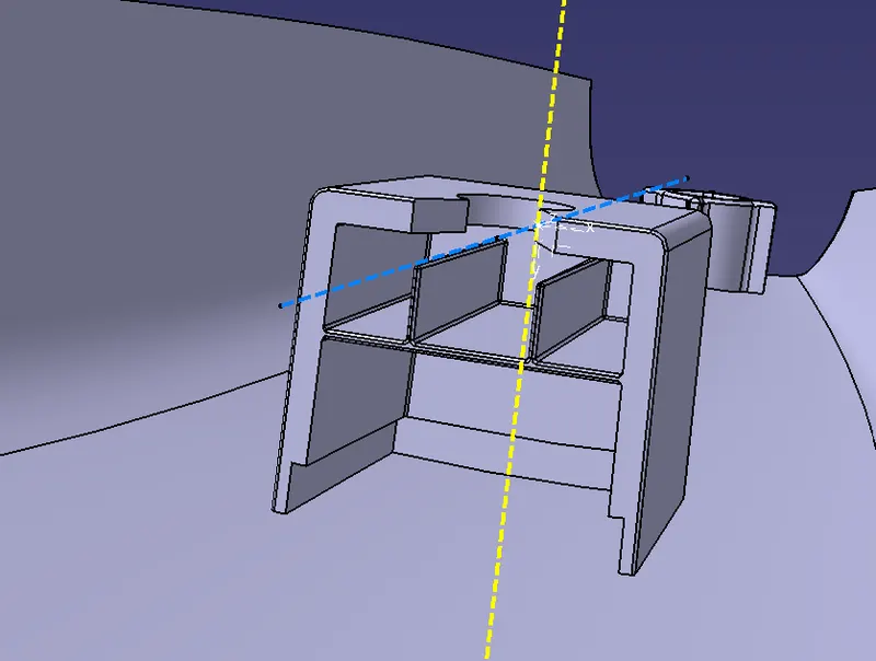
- For the dog house we need a diffrent tooling direction for giving draft angle to the interior part, so a new tooling axis called side core axis is created.
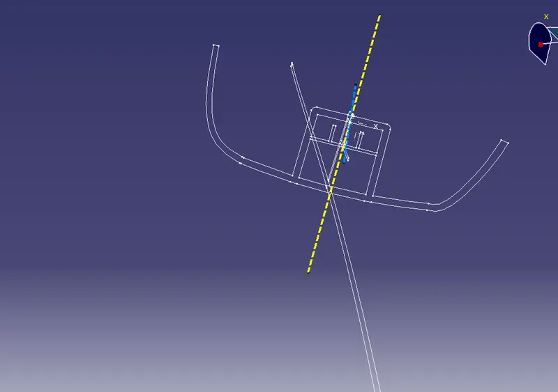
Here the axis in yellow is the main tooling axis and axis in blue is side core axis.
CLASS B CREATION
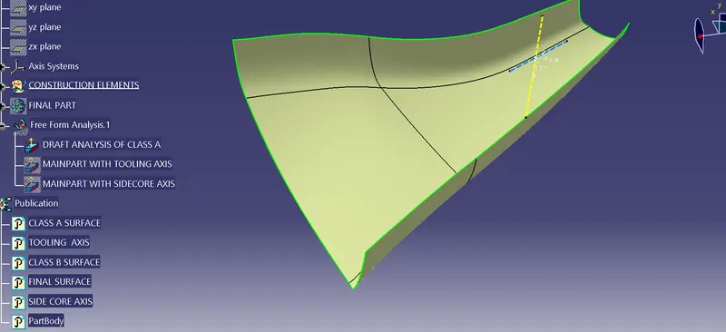
Class B is created by offsetting Class A surface and there will be many patches when we do so, the solution is to fill these patches by using extrapolating, trimming and joining the surfaces together and using multisection for some areas to fill.
CLASS C CREATION AND FINAL TRIM
Class C is created by forming a boundary using Class A surface and using that boundary to perform sweep function with reference to the body at 90 degree and we will get a C surface which is then joined with the A surface to form a combined body which is then trimmed with Class B to get the final part, some extrapolations at the joining ends maybe needed for this procedure and finally the part body is created using closed surface.
DOGHOUSE AND LOCATORS CREATION
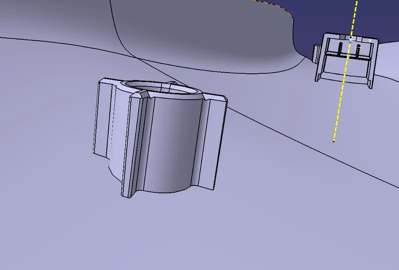
Doghouse is used to provide strength to a fixation element like screws to avoid sinkmarks and locators are used to fix 2 objects and to arrest all degree of freedom, they are created by sketching the required shape and using pad to solidify it and by using translation option they are copied to the required points on the surface.Doghouse is created by using master section provided in the Class A surface, the lines from the master section is padded and operations like drafting, filleting is done further on the surface.