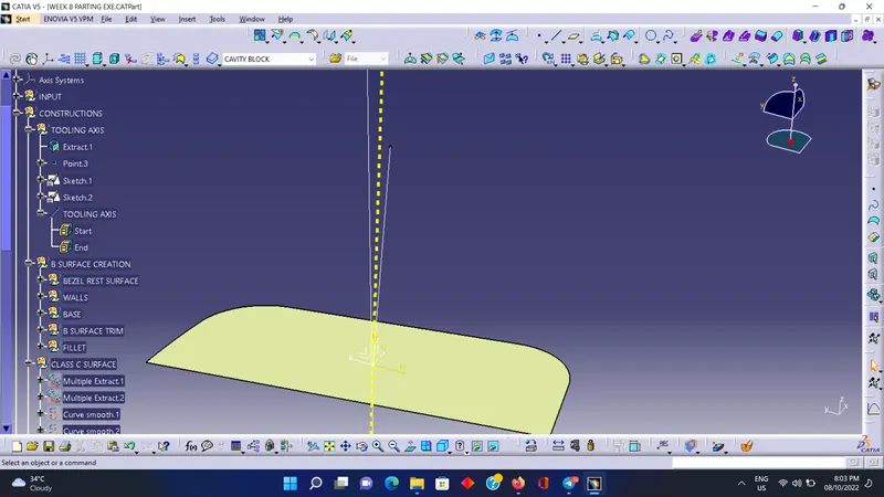
Week 8 - Challenge 6 - Core & Cavity Design
DRAFT ANALYSIS OF FINAL BODY
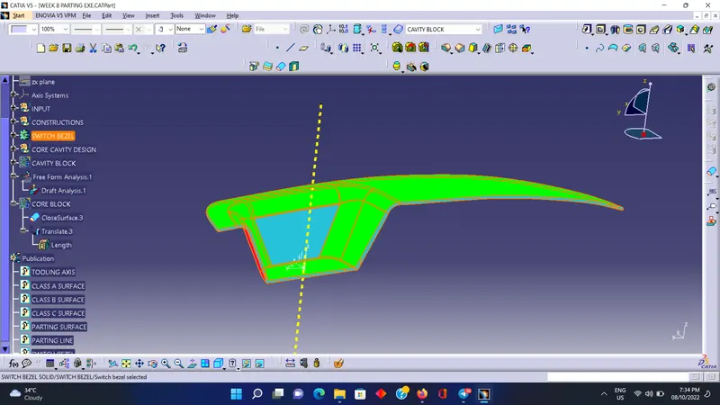
DRAFT ANALYSIS OF CLASS A SURFACE
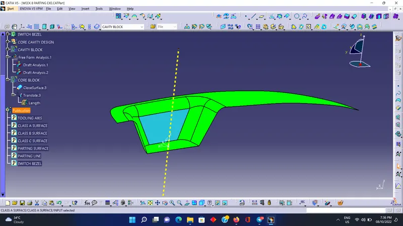
ISOMETRIC VIEW, TOP VIEW , SIDE VIEW AND FRONT VIEW OF CORE AND CAVITY BLOCK
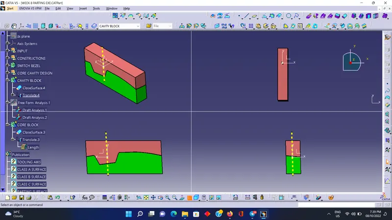
TRANSLATION VIEW OF THE CORE, CAVITY AND PARTING SURFACE
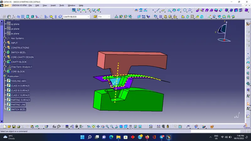
TOOLING AXIS CREATION AND DRAFT ANALYSIS ON CLASS A SURFACE OF SWITCH BEZEL
The main objective is to create Draft Analysis by using tooling direction of class A surface.
- The draft analysis command enables you to identify whether the component you drafted will be easily removed or not.
- After performing draft analysis we will be able to identify the draft angle of each surface of the draft and if it is in the nominal condition which is 3 degree.
- Tooling direction defines you, that in which direction that the component is being removed.
TOOLING AXIS
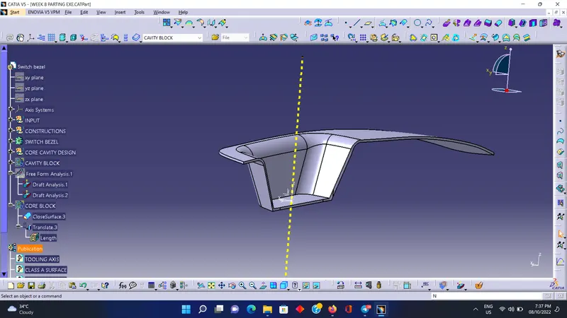
Tooling Axis - Tooling axis is the one of the main construction required for several areas in this design, it is required for the draft analysis of the component and for the direction of the core and cavity translation. Tooling axis is constructed bt bisecting method which is carried out by extracting the base of the switch bezel and creating a line normal to it and a line normal to the whole body and then by creating a bisecting line.