Week 8 - Challenge 3 - Coin Holder Design
TOOLING AXIS CREATION
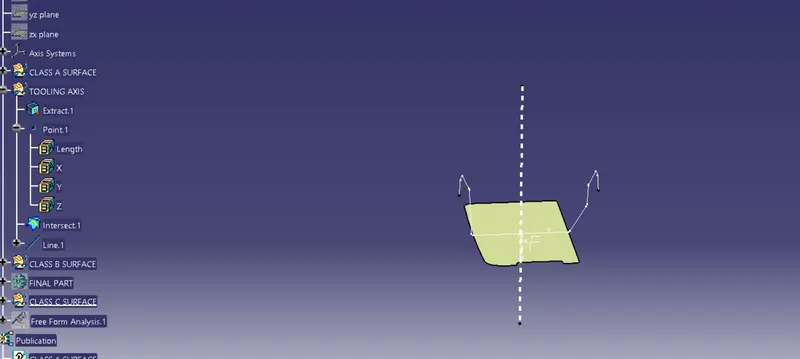
For creating the tooling axis we should consider a suitable area and it is through the tooling axis the component is moved through the core and cavity setting, for this instance we are considering the tooling axis to be normal to the base of the class A surface because of its flat shape and its in 90 degree with the walls.
CLASS A SURFACE
CLASS B SURFACE CREATION
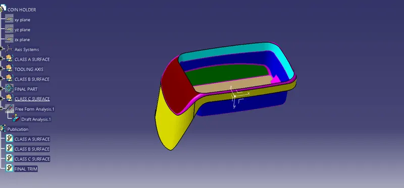
The walls, base and the exterior of the class A surface are extracted leaving fillets to the last part, after extraction they are untrimmed , extrapolated and trimmed together to get the desired class B surface.
CLASS C SURFACE CREATION
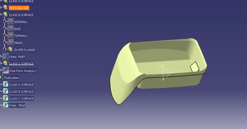
Class C surface is done using the sweep command , in this case the class C is perpendicular to A and B, so the sweep function is done with reference to the class A surface at 90 degree.
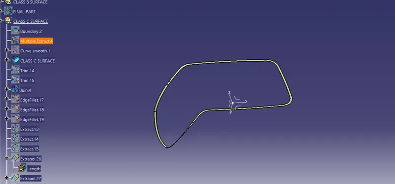
TRIMMIMG AND JOINING
After all this class C is trimmed with class B and then joinned with class A.
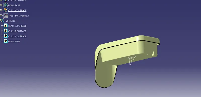
CLOSED PART
It is then converted to a solid part with closed surface .
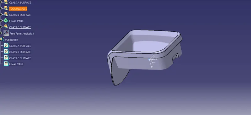
DRAFT ANALYSIS
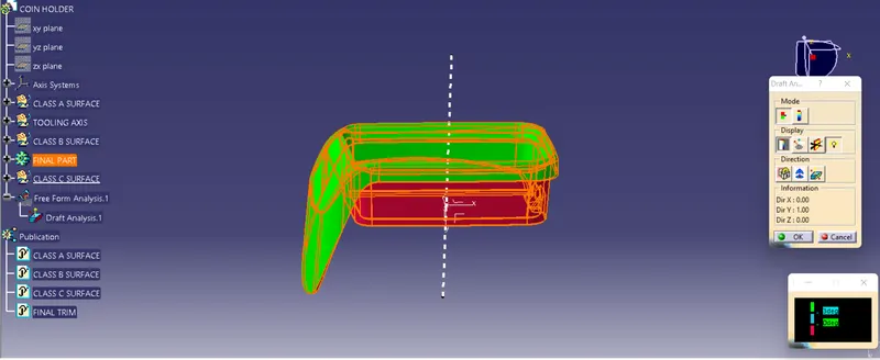
Draft analysis is carried out in this part with respect to tooling axis, a compass is aligned with tooling axis and after locking it we click on the body to get the coloring variation according to the angle, here we have given green for 3 degree and above , blue for zero and red for negative angles.