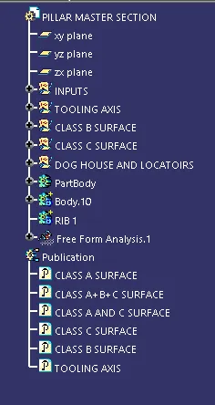
Week 9 - Project - A pillar Design with Master Section
AIM:
To create an A-pillar using the given CLASS-A surface and Master section.
OBJECTIVES:
- Create closed body
- Create tooling axis and follow design rules.
- Follow the Master section to create flange
- Follow the master section for thickness and to create the Closed volume.
- Follow master section to create Attachment features
CLASS A SURFACE AND MASTER SECTION:
Class-A surface is the aesthetic of the component which is created by the styling team and gives to the part design engineer to create the part with all engineering aspects.
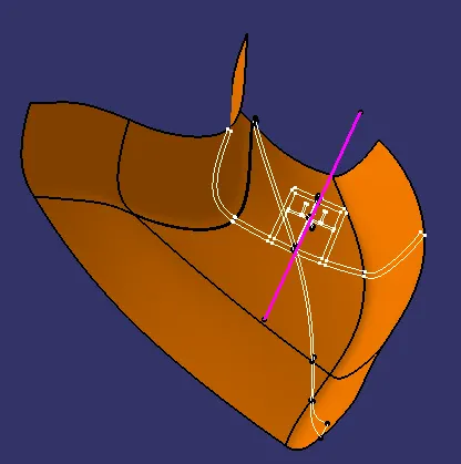
TOOLING AXIS:
Create tooling axis is created using the given master section.
- Create a point on the master section.
- Create planes on the given master sections with respect to the point created.
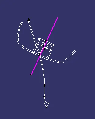
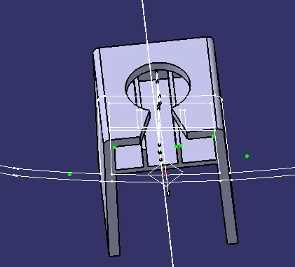
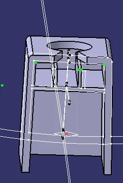
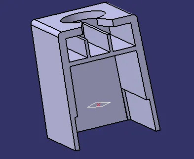
- Using positioned sketch, create lines in the walls of dog house section and then create bisecting line.
- Using the bisecting line 1 and 2, create a new bisecting line which can be selected as the Tooling Axis.
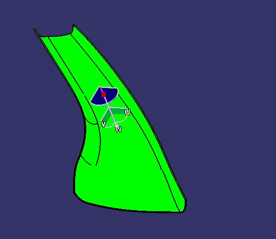
DRAFT ANALYSIS OF CLASS A SURFACE:
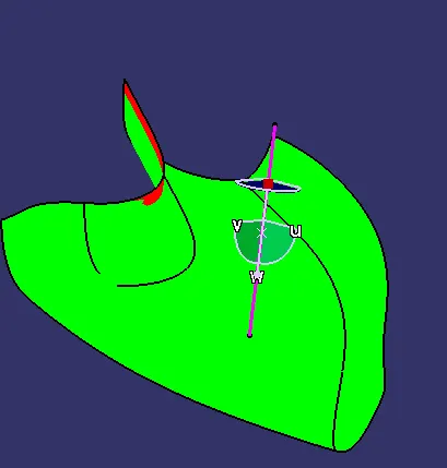
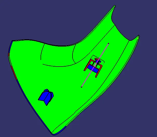
The draft analysis command in CATIA helps to detect whether the drafts provided in the model will facilitate easy removal of the component during manufacture.
This analysis is performed based on colour ranges identifying zones on the analyzed element where the deviation from the draft at any point, corresponds to specified values.
- When the draft angle value of the surface is equal or smaller than a graduated value, the color below the graduated value is applied
- When the draft angle value of the surface is greater than the greatest graduated value, the color above this graduated value is applied
In this project, the required draft for all surfaces were chosen as 3 degrees.
CLASS B SURFACE:
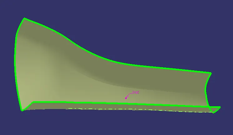
- Once the analysis on the class-A model was done the next step was to create the B-Surface for the model
- The Class-A Surface features were analysed and according to the B-surface creation procedure followed in this project, different regions were selected and assigned different colours and appropriate names
- he surfaces to be made into the B surface were first extracted using the extract tool
- To remove dependencies with the original surface, these extracted surfaces were then made independent using the tool
- In order to join these independent surfaces, they needed to be extended to form interference between adjacent surfaces. For this the extrapolate tool was used
- To remove unwanted extensions in the surfaces after interference, the trim tool was used and the result was a single surface
- Since the idea behind creation of a B surface is to have an offsetted surface from the input class A surface, the next tool used was the offset tool.
CLASS C SURFACE:
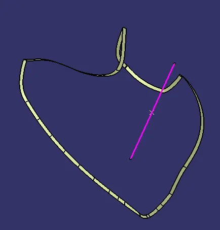
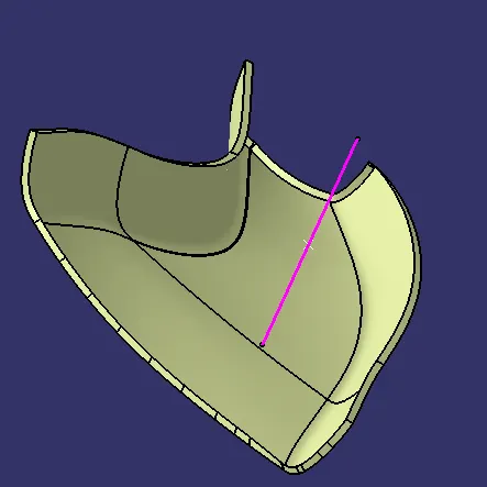
- The C surface forms the connection between the Class-A and B surfaces and is essentially the thickness of the final component
- The C surface was formed using the sweep tool
- For this command, the side flanges and its boundary were extracted from the Class-A Surface and then swept to form the C surface
CLASS A+C SURFACE:
CLASS A+B+C SURFACE:
FINAL BODY:
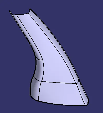
- Before converting the surface model into a solid model, the part was first opened using in the part workbench
- The close surface tool was used to convert the surface model into a solid model
DRAFT ANALYSIS OF FINAL BODY:
DOG HOUSE CREATION:
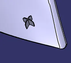
LOCATORS:
FINAL DRAFT ANALYSIS OF BODY:
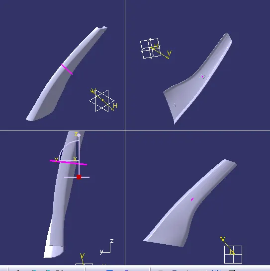
FINAL BODY IN MULTI SECTION:
FULL TREE: