Week 9 - Project - A pillar Design with Master Section
AIM
To design A-Pillar with master section
OBJECTIVE
- Create closed body
- Create tooling axis and follow design rules.
- Follow the Master section to create flange
- Follow the master section for thickness and to create the Closed volume.
- Follow master section to create Attachment features
THEORY
DOG HOUSE DESIGN :-
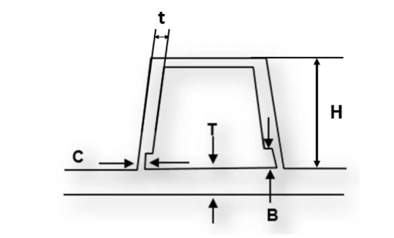
figure 1. dog house
- Height of the Dog House - Maxiumum of 55 mm
- Thickness of the Dog House (t) - Same as component wall thickness
- Coring Height (B) - 3 mm to 6 mm
- Coring Thickness (C) - 40% of Wall Thickness of the component
- Thickness of the Component - Given as input
- Length and Breadth of the Dog House can be decided upon the application
- Inner Fillet of Dog House (Thickness t) - 0.5 mm
- Outer Fillet of Dog House (Thicknes t) - t + 0.5 mm
- Inner Fillet of Dog House (Thickness C) - [ t + 0.5 mm] - 40% of Wall Thickness
- Outer Fillet of Dog House (Thicknes C) - t + 0.5 mm
- Fillet for the Corting Face - 0.25 mm (or) 0.3 mm
- Draft Angle for Dog House - 0.5 degrees (both outer & inner)
RIB DESIGN :-
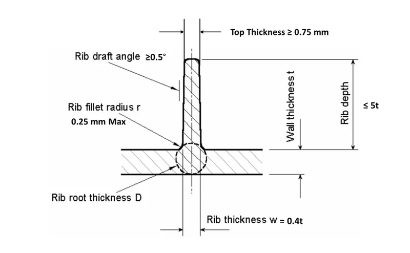
figure 2. rib design
- Maximum Height of the Rib - Less than or equal to 5 x Wall Thickness of the Component
- Minimum Fillet Radius of the Rib - 0.25 mm (or) 0.3 mm
- Minimum Draft Angle of the Rib - 0.5 degrees
- Rib Thickness - 0.4 x Wall Thickness of the Component
- Rib Top Thickness (after applying draft) - >= 0.75 mm
- Rib Root Thickness - 1.4 x Wall Thickness of the Component
- The minimum distance between the two ribs is 50 mm
- The length of the rib depends upon the application
TOOLING AXIS
Here tooling axis is created by using the master section. First created the section axis-1 from first section and section axis-1 created from the second section. Finally created the tooling axis by create a bisecting line using section axis-1 and section axis 2.
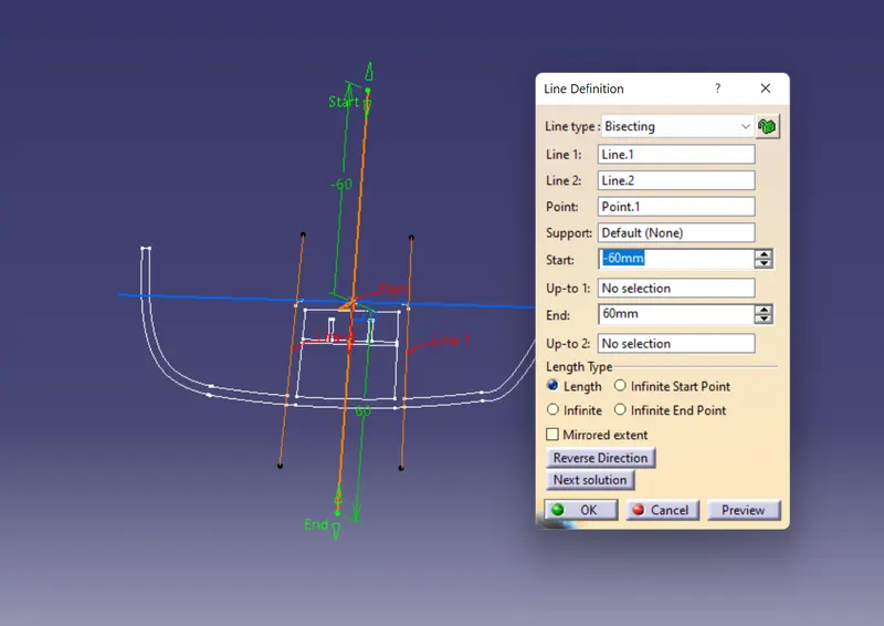
figure 3. section axis 1
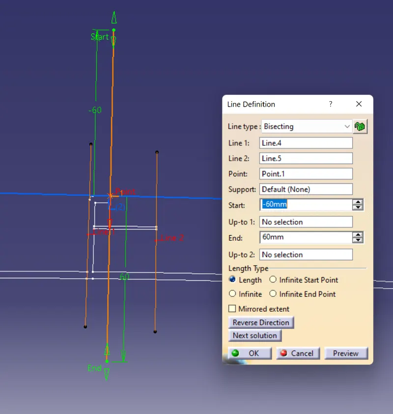
figure 4. section axis 2
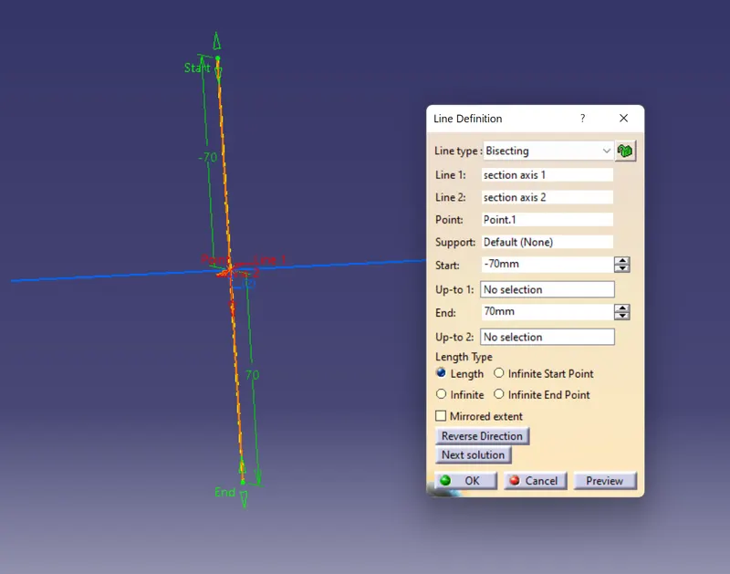
figure 5. tooling axis
SIDE CORE AXIS
Create a plane using first section as shown in the figure. That is plane 1. Create a line normal to plane 1 for creating side core axis.
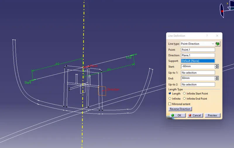
figure 6. side core axis
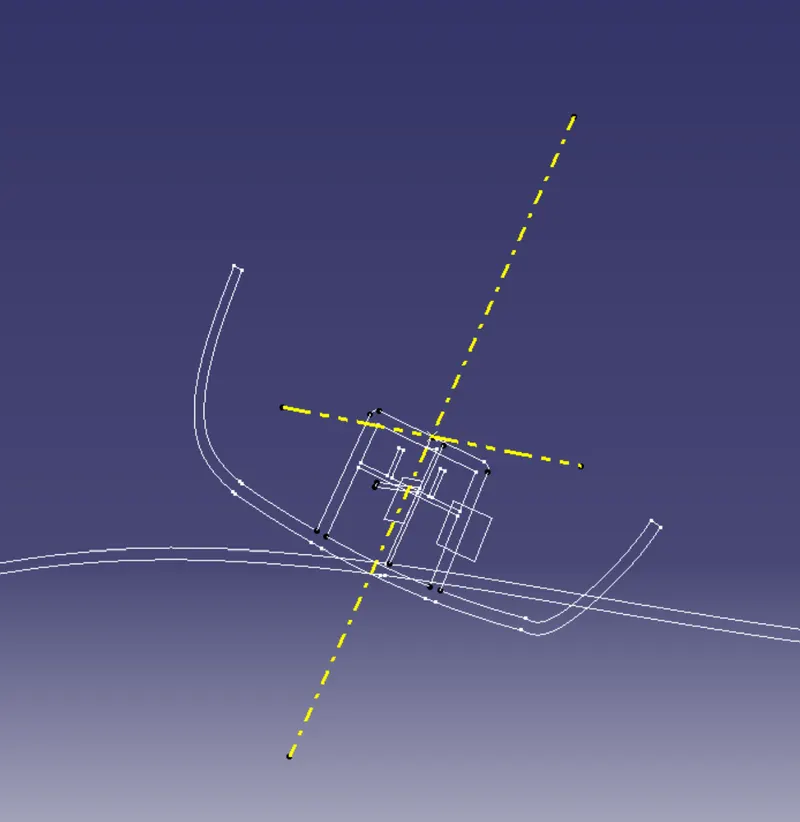
figure 7. tooling axis and side core axis
DRAFT ANALYSIS OF CLASS A SURFACE
Here draft analysis carried for class A surface with respect to tooling axis. Here colour code used is a green colour indicating that the draft is 3 degree or above. The red colour indicates that the draft is 0 and between 0 degree and 3 degree and the blue colour indicates that the draft is minus value. From draft analysis we can see that green colour is all over the surface except for some part shown in the figure.
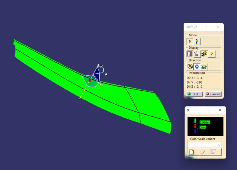
figure 8. class A draft analyisis
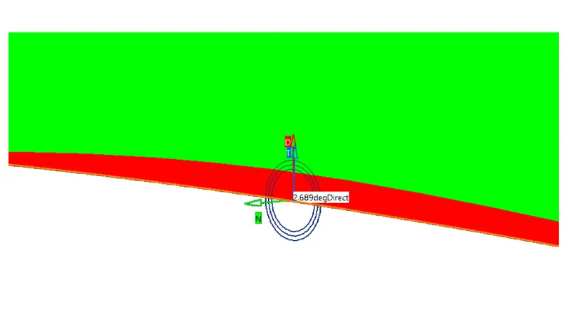
figure 9. class A draft deviation
DRAFT ANALYSIS OF A MODEL
Here we need to check the draft of A-Pillar, dog house and ribs along tooling axis. First check for the A-Pillar, we have to set colour for the draft analysis with minimum draft of 2.98 degrees. Here colour code used is a green colour indicating that the draft is 2.98 degree or above. The red colour indicates that the draft is 0 degree and the blue colour indicates that the draft is minus value. From draft analysis we can see that green color over the surface of the A-Pillar except for some part due to class A draft issue. That is shown in the figure.
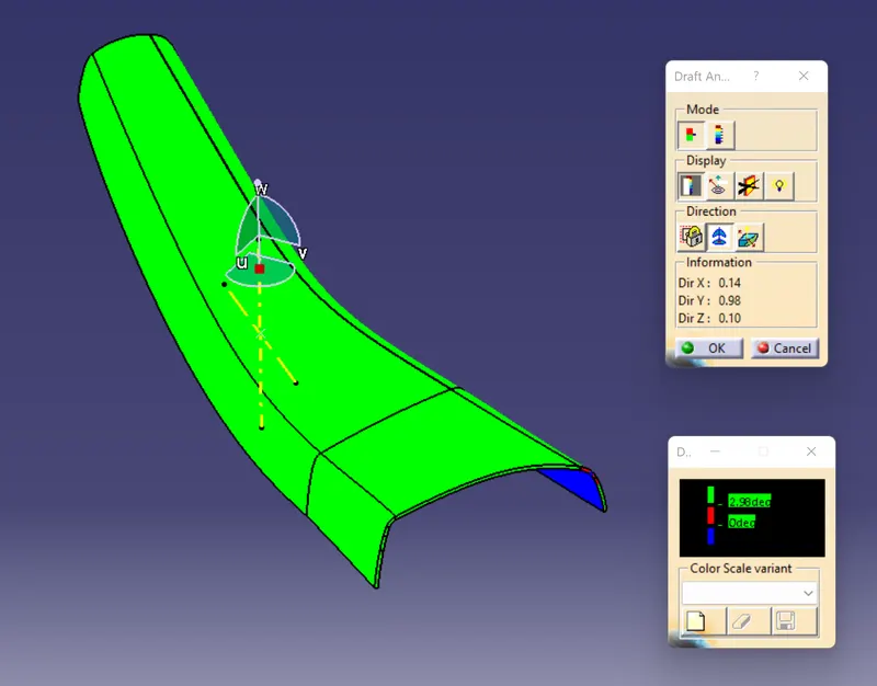
figure 10. model draft analysis
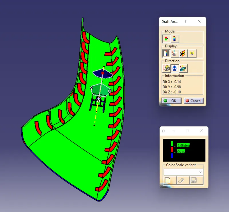
figure 11. model draft analysis
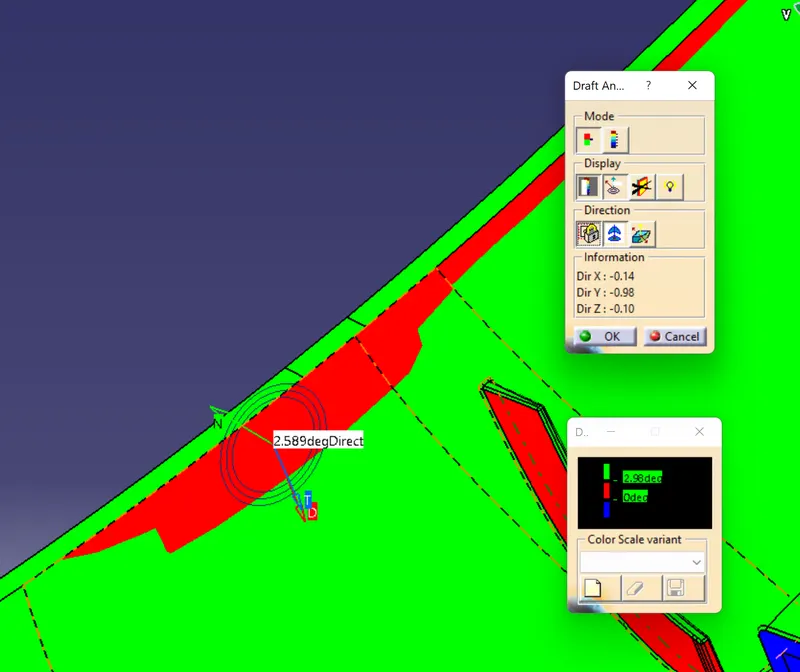
figure 12. model draft deviation due to deviation in class A surface
Next we have to check with the door house and ribs along tooling axis. Here we have to set colour for the draft analysis with minimum draft of 0.48 degrees. Here colour code used is a green colour indicating that the draft is 0.48 degree or above. The red colour indicates that the draft is 0 degree and the blue colour indicates that the draft is minus value. From the draft analysis we can see that outer surface of the dog house clear with 0.48 degree draft with tooling axis and rib surfaces also clear draft of 0.48 degree.
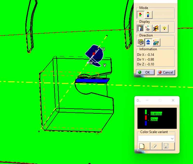
figure 13. dog house outer draft analysis
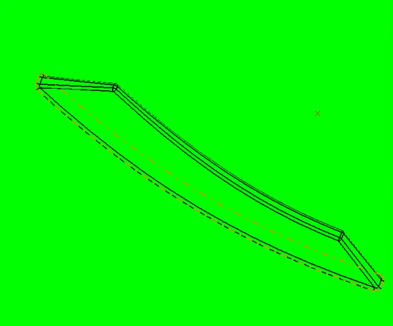
figure 14. rib draft analysis
Next we have to check the inside of dog house with side core axis. Here we have to set colour for the draft analysis with minimum draft of 0.48 degrees. Here colour code used is a green colour indicating that the draft is 0.48 degree or above. The red colour indicates that the draft is 0 degree and the blue colour indicates that the draft is minus value. From the draft analysis we can see that inner surface of the dog house clear with 0.48 degree draft.
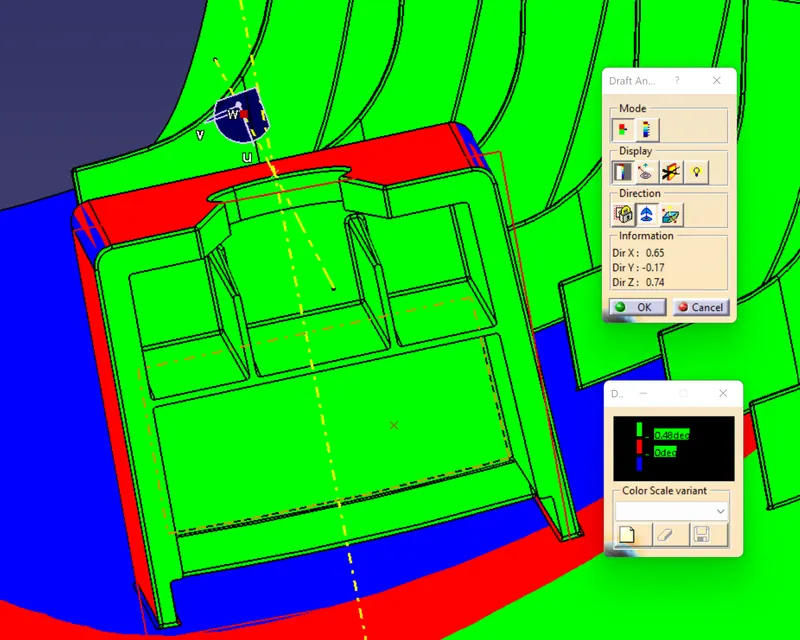
figure 15. dog house inner draft analysis
MODEL VIEWS
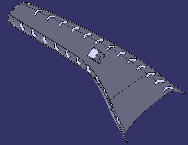
figure 16. isometric view
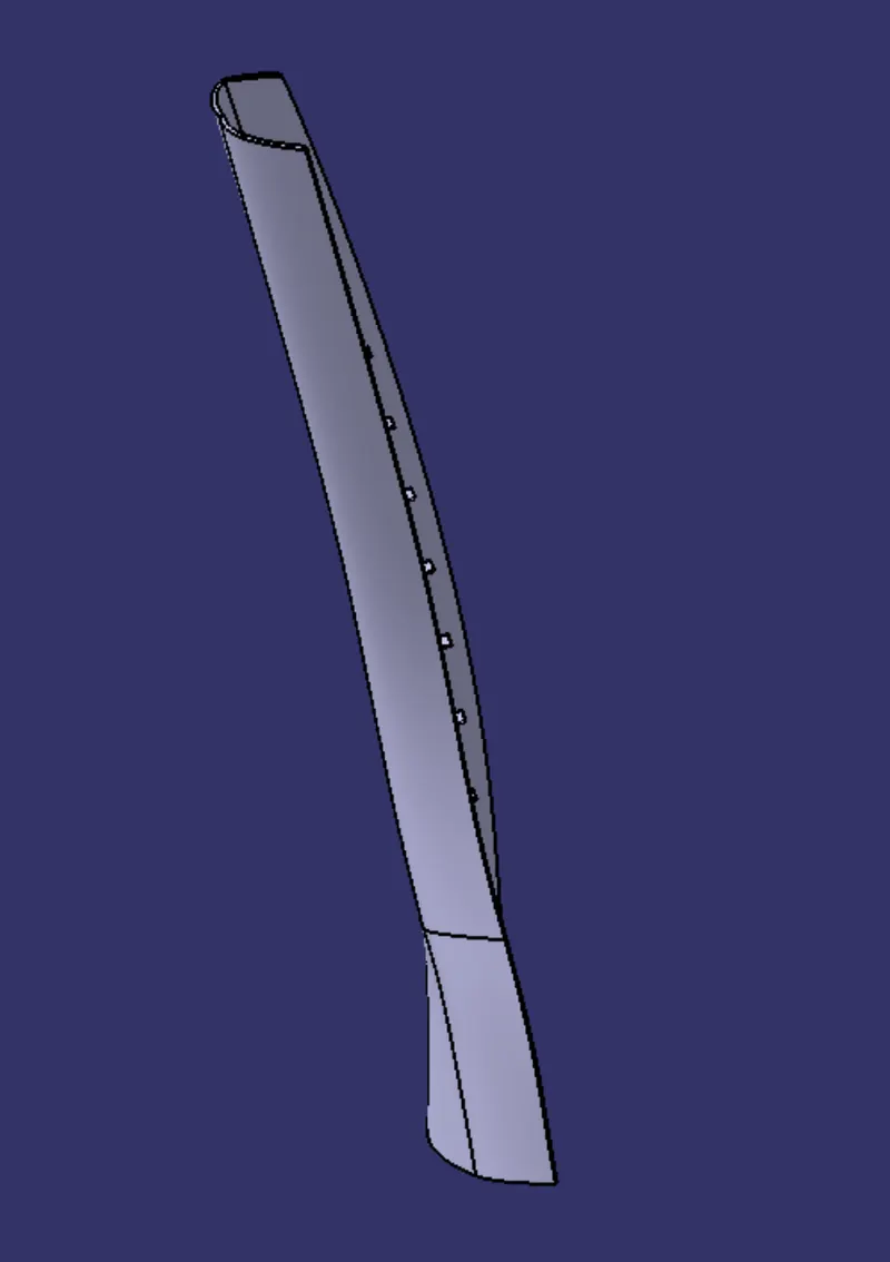
figure 17. front view
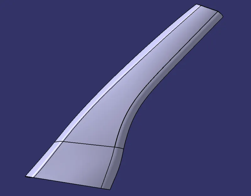
figure 18. left side view
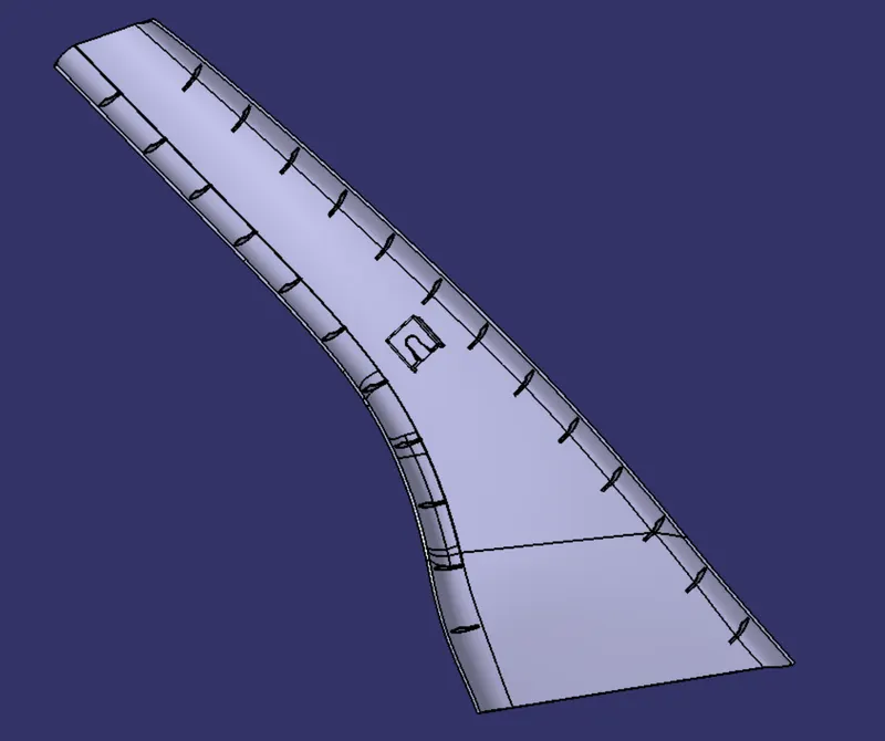
figure 19. right side view
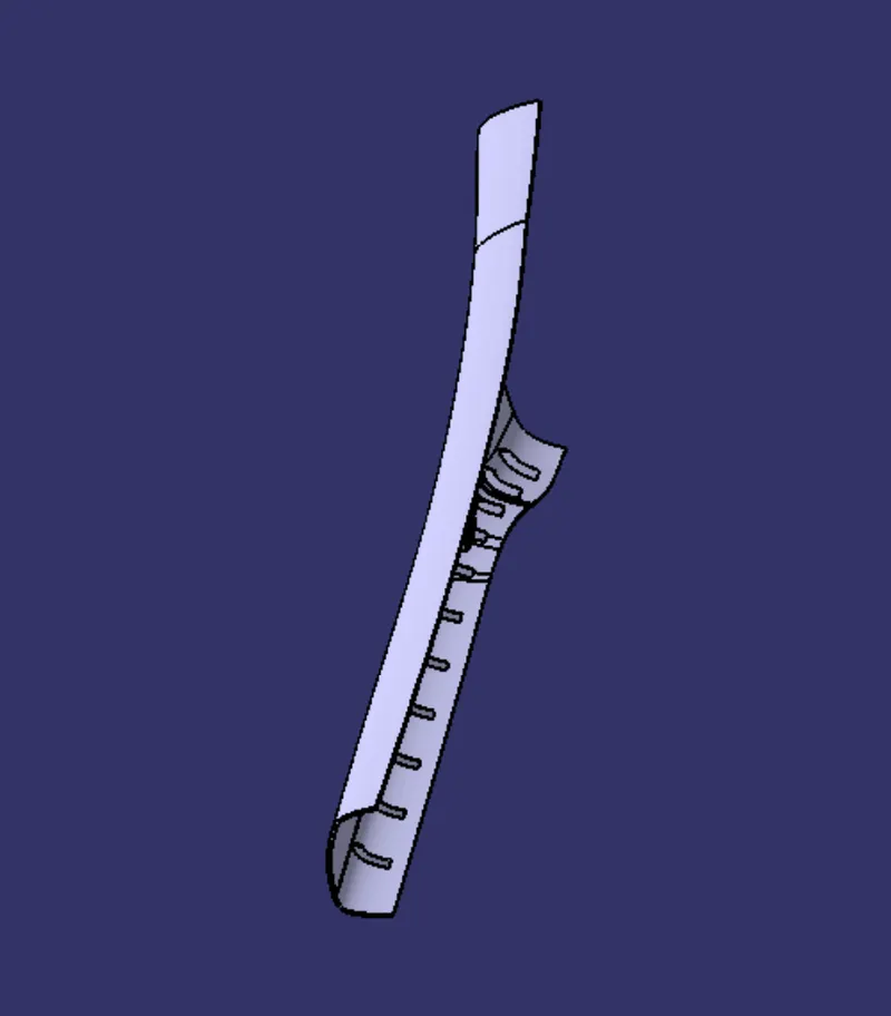
figure 20. top view
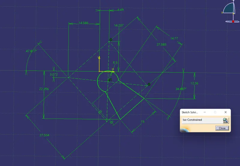
figure 21. key hole sketch in dog house
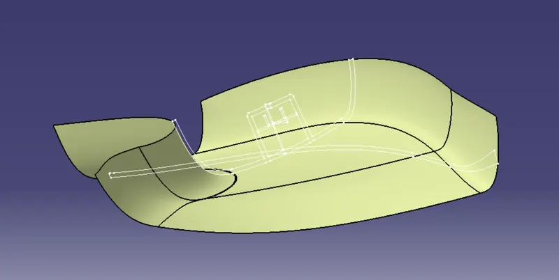
figure 22. class A with master section
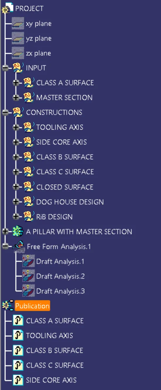
figure 23. tree structure
CONCLUSION
A-Pillar designed according to the master section.