Week 9 - Project - A pillar Design with Master Section
AIM: Design of A Piller using Master section
Master Section: REFERENCE FOR CLASS A, CLASS B & CLASS C SURFACE
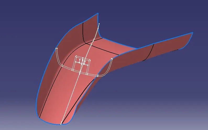
Design Approach:
- Creating the B and C surface
- Creating the tooling axis
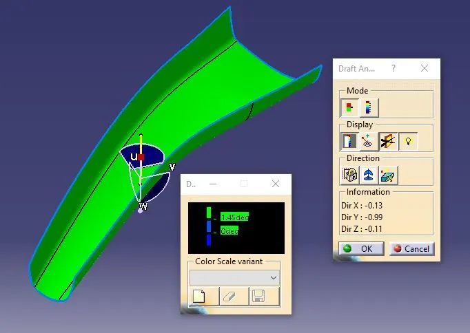
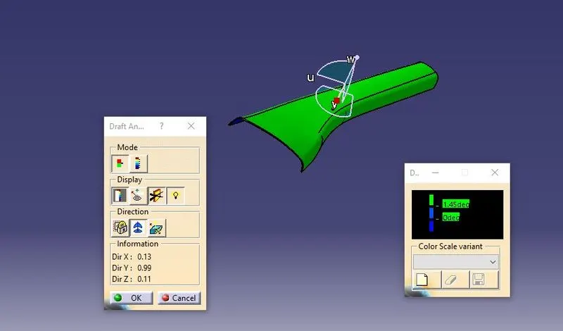
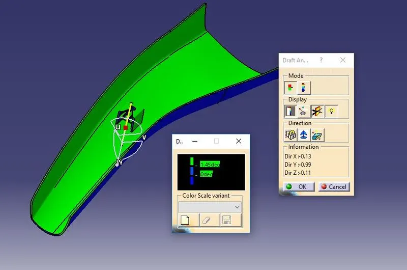
- Performing the draft analysis on both A surface and Closed plastic components.
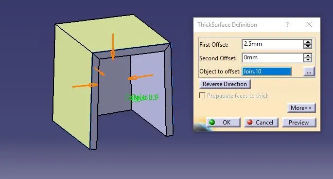
- Take the Thickness of the component to be 2.5 mm
- Create Profile (Dog House, Ribs & Pocket) using master section
- Do draft analysis of newprofile and final component
Class A SURFACE
- Visible surface and aesthetic look
- Surface with textures
- Surfaces provided by Customer (OEM)
- Don’t have any features like (rib, snap, bosses, etc) on class A surface.
- Class A surface is made from scanned data with different software like alias etc.
- Surfaces which are having CURVATURE CONTINUITY IS CALLED class-A.
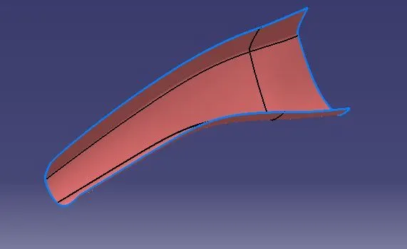
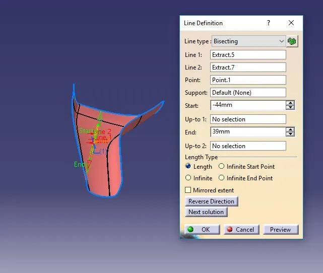
CREATING TOOLING AXIS:
- Intersected the plane on class A
- connected two out points by line.
- Excruded the line by taking the point on the surface
CLASS A DRAFT ANALYSIS
CLASS B SURFACE IS:
- Invisible Surfaces.
- Surface mostly don't have textures
- Surface needs to be created according to the class-A surface.
- Having all features in B-side surface only.
- Surfaces which is having TANGENT CONTINUITY IS CALLED class-B
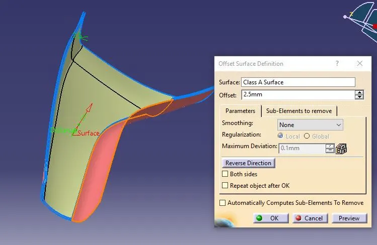
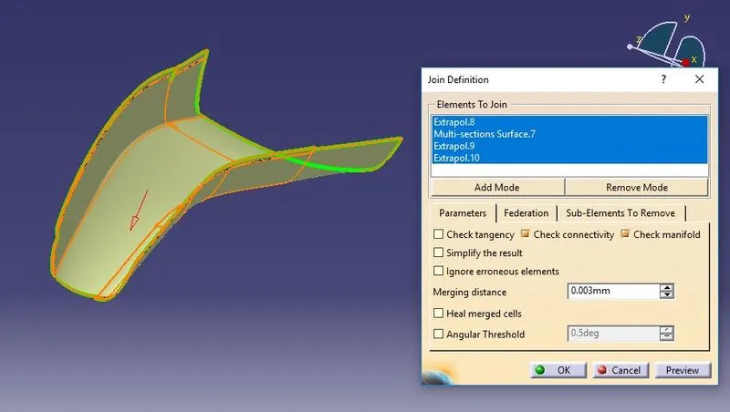
Just offseted the Class A for 2.5mm & performed some modifications as per requirement.
CLASS C SURFACE:
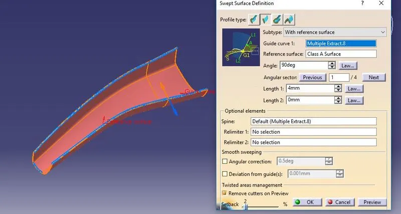
Took a boundry for class A
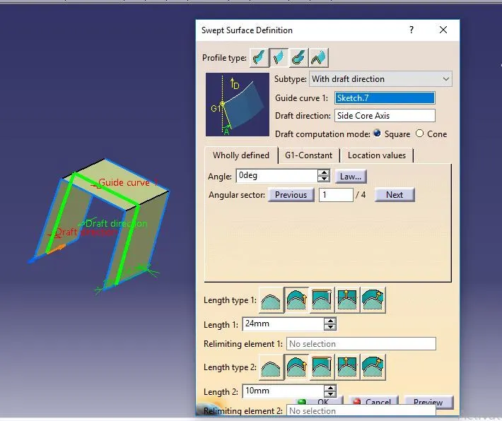
Sweept using boundry & Reference surface.
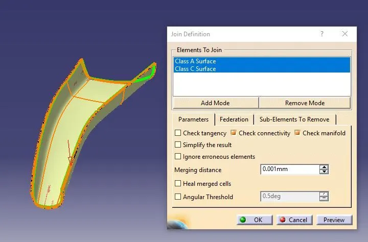
CLASS A+C SURFACE:
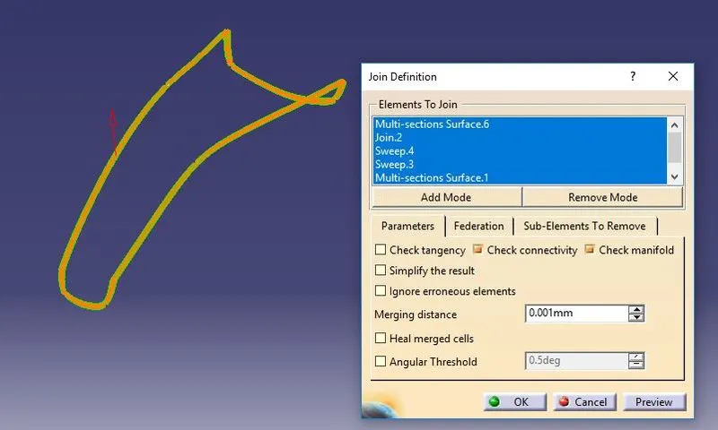
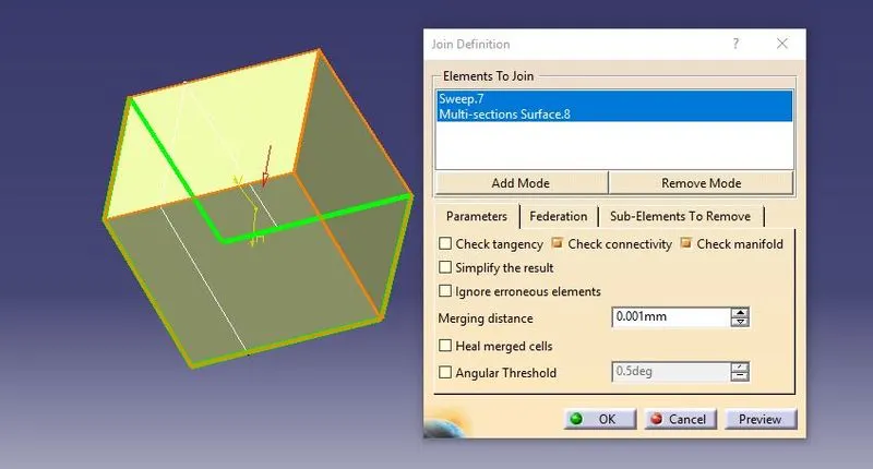
Join the class A & c surface together
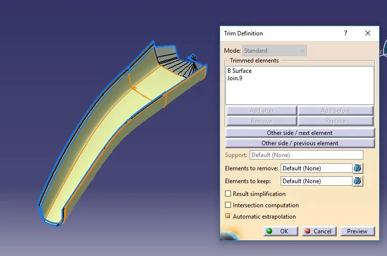
FINAL TRIM SURFACE:
Trimed Class A,Class C with Class B
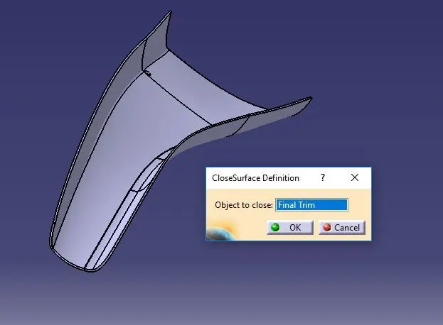
CLOSED SURFACE:
Draft Analysis Closed surface:
B Side Features:
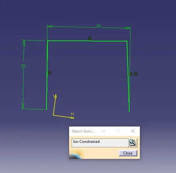
DOG House & Ribs using Master Section:
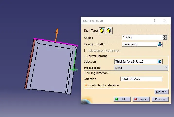

Ribs:
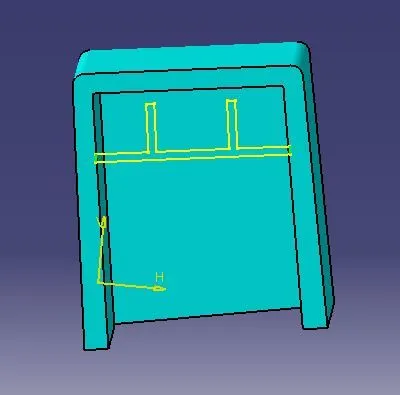
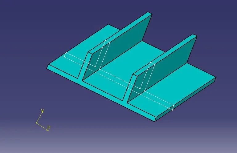
Draft Analysis Dog house:
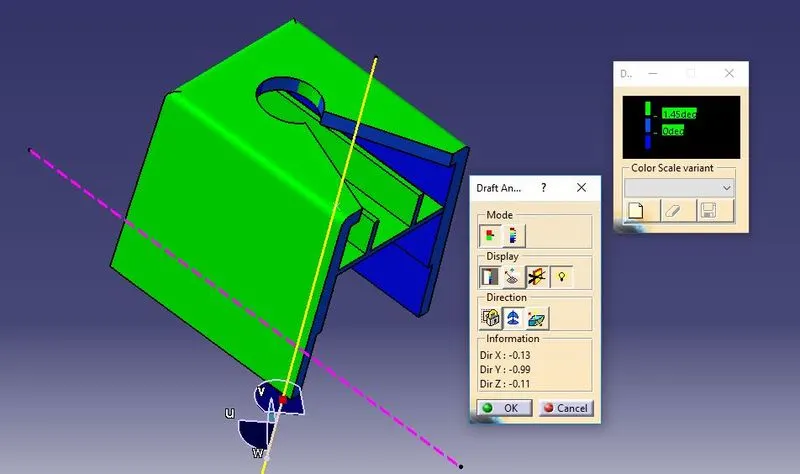
Draft Analysis Final Componenet:
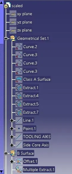
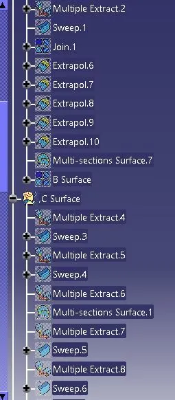
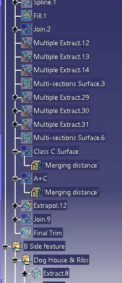
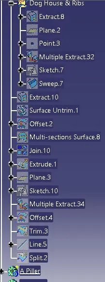
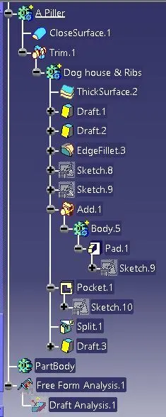
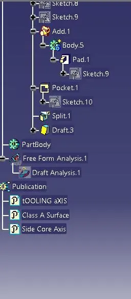
Feature Tree:
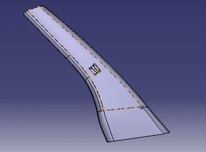
Different View:
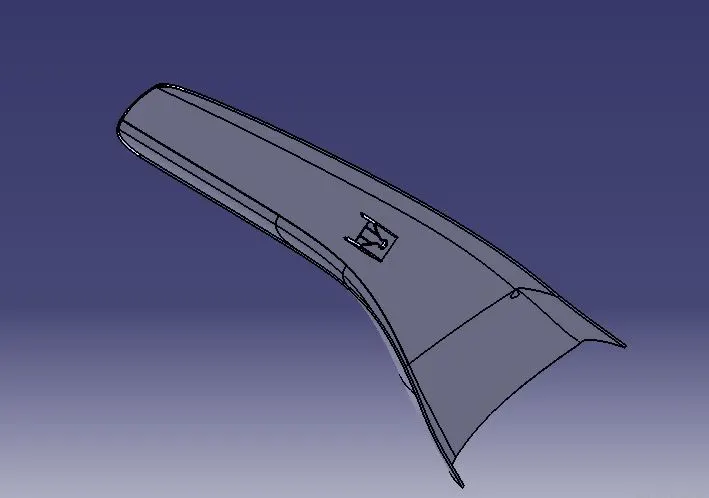
1) Isometric View:
2) Front View:
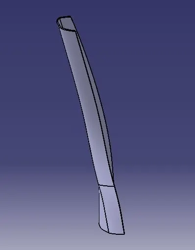
3) Top View:
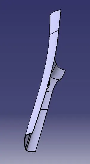
4) Right Side Views:
Conclusion: Thus I Craeted the A Piller usxing Master Section