Week 9 - Project - A pillar Design with Master Section
Object:- Design of A pillar Design with Master Section
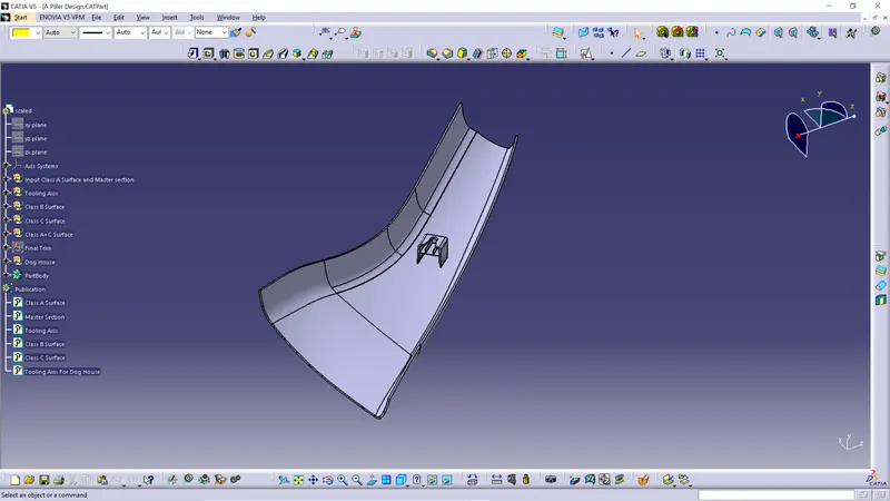
Class A Surface:-
The Class-A modelling process typically starts with a fully developed design, either as a scanned clay model or an Alias model. Because the design isn't changing, the modeller has the time to build surfaces to the highest quality standards, ready for production.
The challenge for Class-A is to combine the need for:
- Aesthetic Quality - Continuity and Highlights
- Engineering Requirements - Flanges and Fit
- Production Requirements - Modelling Tolerances
Baseline Requirments G1,G2 & G3
The baseline requirements for Class-A are the same as for production-quality surfacing in all industries: to build to tight tolerances for G0, G1 and G2 continuity.
In Alias this is achieved by using the right Construction Tolerances before you start modelling, for example 'Catia V5'.
Class B Surface:-
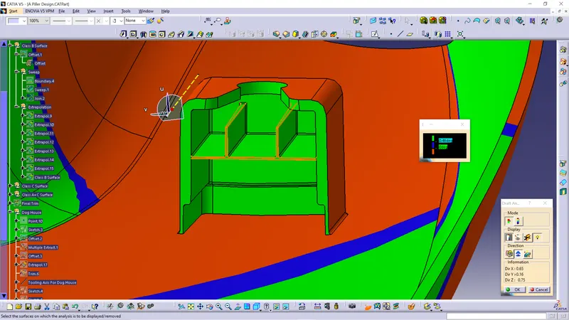
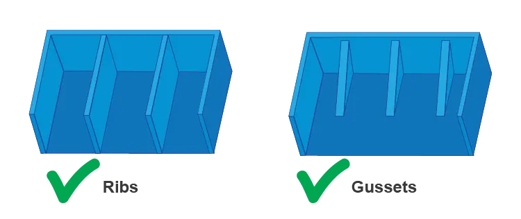
Class B Surface is availble opposite side of class A Surface where all the engineering features are build and class B surface are not directly visible to constumer that's why all engineering features like Dog house, Heat Stakes, Rib, Locators are build on class B surface.B surface means thickness of a part it is not visible it is inside part.
Class C Surface:-
A surface means visible surface.it will give styler.B surface means thickness of a part it is not visible it is inside part. c surface means A and B combined to give C surface. Draft agnle is play main role during making the Class C surface.
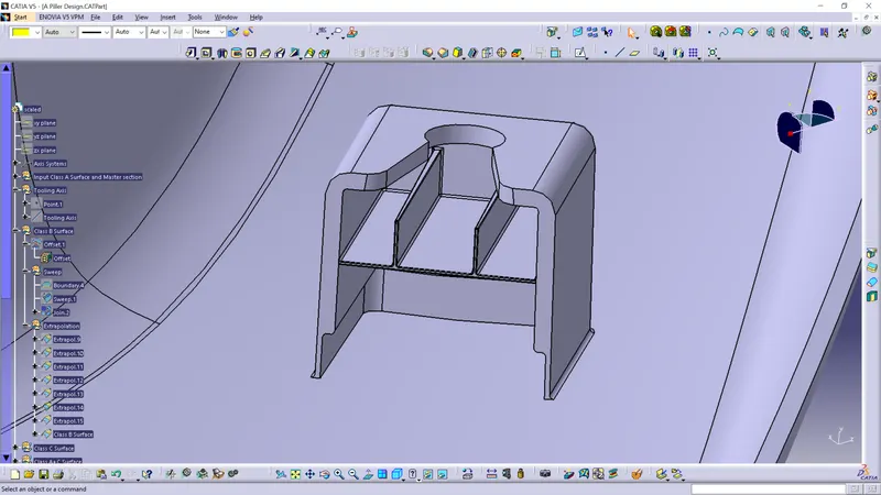
1.WALL THICKNESS:
Thick sections waste material and are simply uneconomic. So solid shapes that would do the job well in wood or metal must be transformed to a 'shell' form in plastics. This is done by hollowing out or 'coring' thick parts so you are left with a component which regardless of complexity is composed essentially of relatively thin walls joined by curves, angles, corners, ribs, steps and offsets. As far as possible, all these walls should be the same thickness. Wall thickness guide range is 0.75 mm to 3 mm for reinforced materials 0.5 mm to 5 mm for unreinforced materials.
Wall thickness = As material thisckness
Coaring wall Thickness = Guide range is 40% of material thisckness
2.DRAFT ANGLE:Tooling must be cleared for easy ejection of the component, from the core cavity. In order to clear tooling certain value of draft is given to the component. Minimum of 2-3deg is provides on all plastic components.
Minimum draft angle for the for all engineering features is 0.5 Degree (According to Skill-Lync data)