Week 9: Project 1 - Surface preparation and Boundary Flagging (PFI)
AIM:
Surface preparation and boundary flagging.
OBJECTIVE:
- Import the CAD model of ic engine into converge and run diagnosis.
- Setup the case for no hydrodynamic simulation and to create animation in paraview.
INTRODUCTION:
GEOMETRY SETUP:
- IMPORT GEOMETRY:
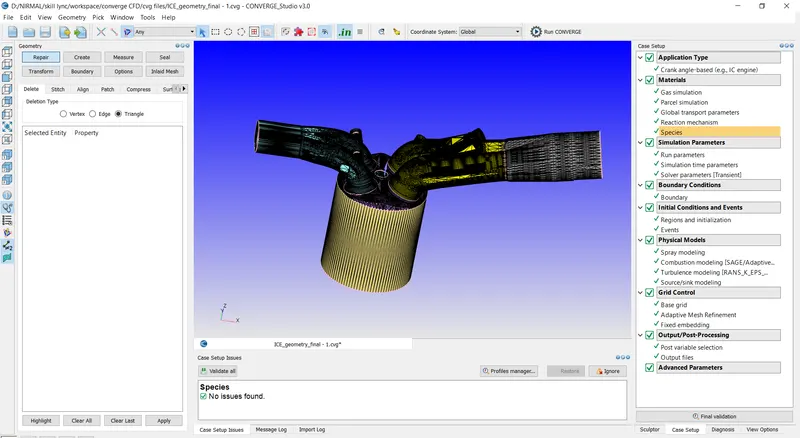
Geometry that is provided .stl is imported to the workspace.
- NORMAL ORIENTATION:
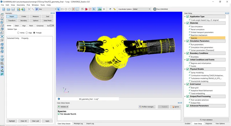
The orientation of normal are checked and its changed such that the normal points inwards by going to transform > normal
- CREATING BOUNDARIES:
The boundary are created for the geometry under boundary flag tab.
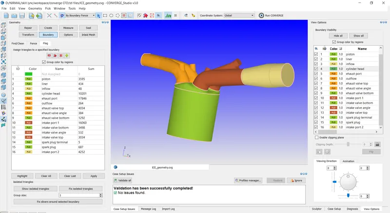
The boundaries are assigned to the faces and the name of the boundaries are edited and click apply.
- DIAGNOSIS:
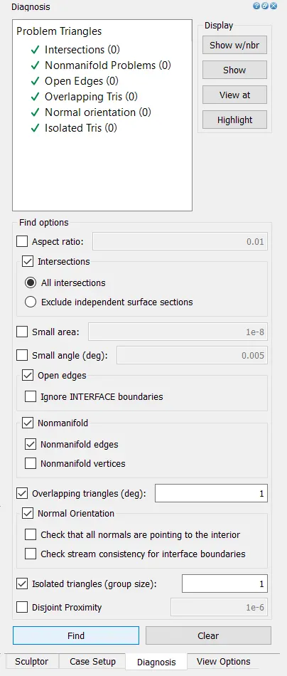
The diagnosis is runed and checked for problems for the geometry.
BEGIN CASE SETUP:
- APPLICATION TYPE:
On the right panel go to the case setup tab, select begin case setup.
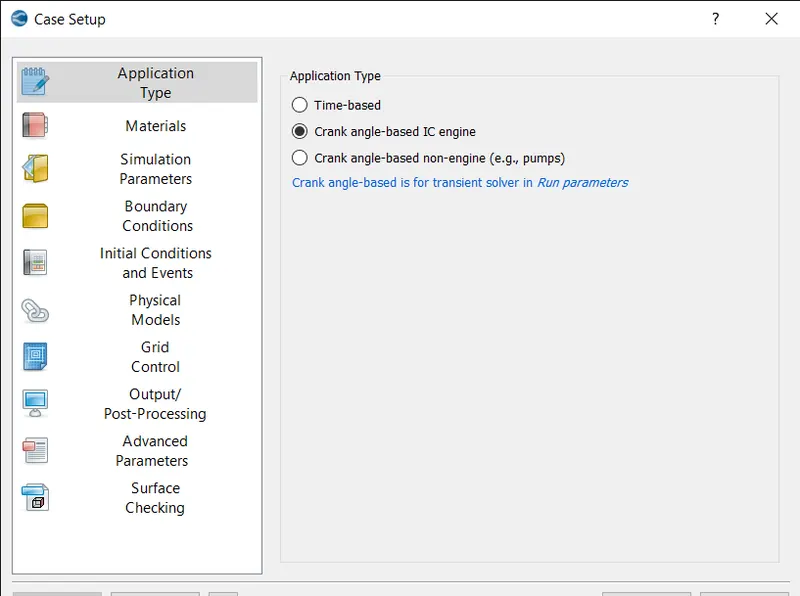
Select the application type as crank angle based ic engine and select apply and done.
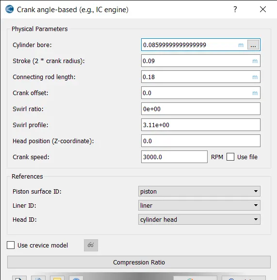
The physical parameters are applied.
- MATERIALS:
Select materials and select the checkbox reaction mechanism and then click apply and done.
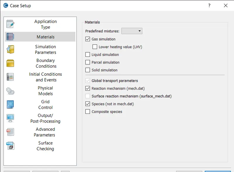
- GAS SIMULATION:
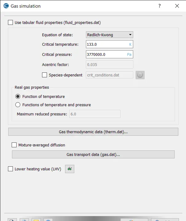
The default values are selected and press ok.
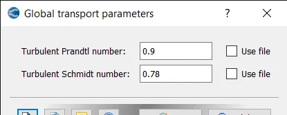
- GLOBAL TRANSPORT PROPERTIES:
Select global transport properties, keep the default values and press ok.
- REACTION MECHANISM:
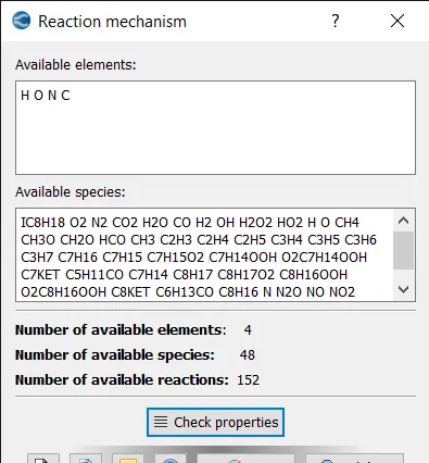
The species are added and checked the properties and click apply.
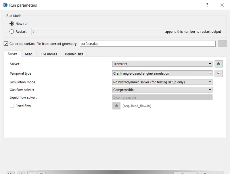
- RUN PARAMETERS:
Under solver tab select solver as transient solver.
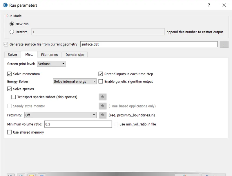
- MISC TAB:
Under misc tab uncheck use shared memory option and click ok.
- SIMULATION TIME PARAMETERS:
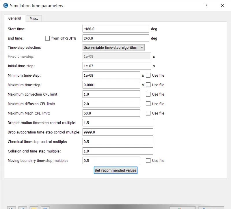
Set the start time, end time, initial, minimum and maximum time steps as shown above.
- SOLVER PARAMETERS:
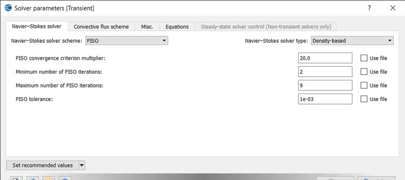
Select the Navier-stokes solver type as density based and click ok.
- REGIONS AND INITIALIZATIONS:
CYLINDER REGION:
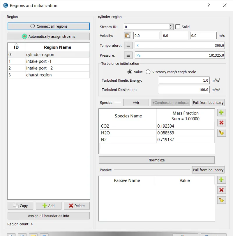
The cylinder region is created and the species co2, h2o and n2 is added.
INTAKE PORT 1 REGION:
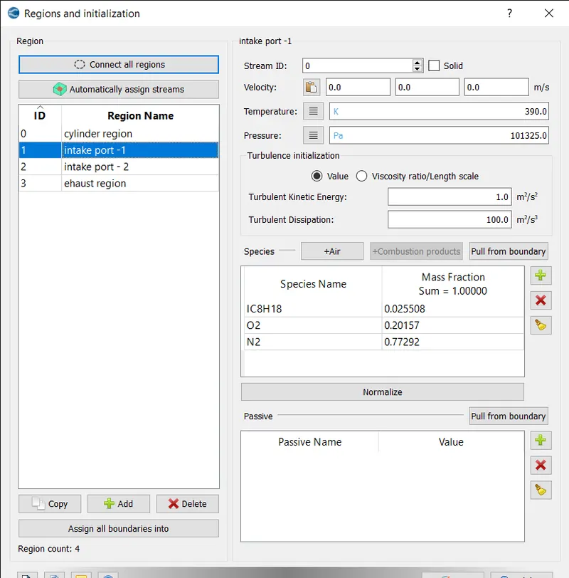
In the intake port 1 region the temperature is set to 390k and pressure as atmospheric pressure and ic8h18, o2 and n2 are added as species.
INTAKE PORT 2 REGION:
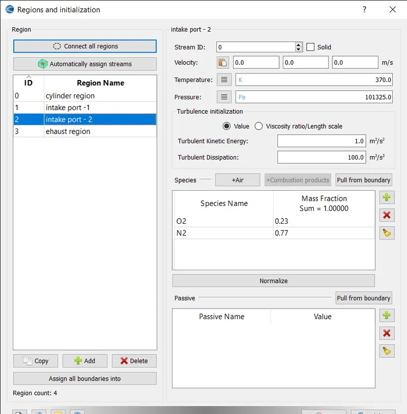
in this region temperature is set to 370 k and pressure as atm and air is added as species.
EXHAUST REGION:
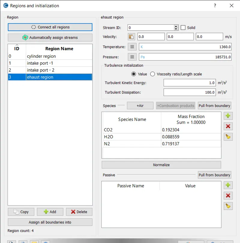
In this region temperature is set to 1360k and temperature as 185731pa and co2 , h2o and n2 are added as species.
- BOUNDARY CONDITIONS:
PISTON BOUNDARY:
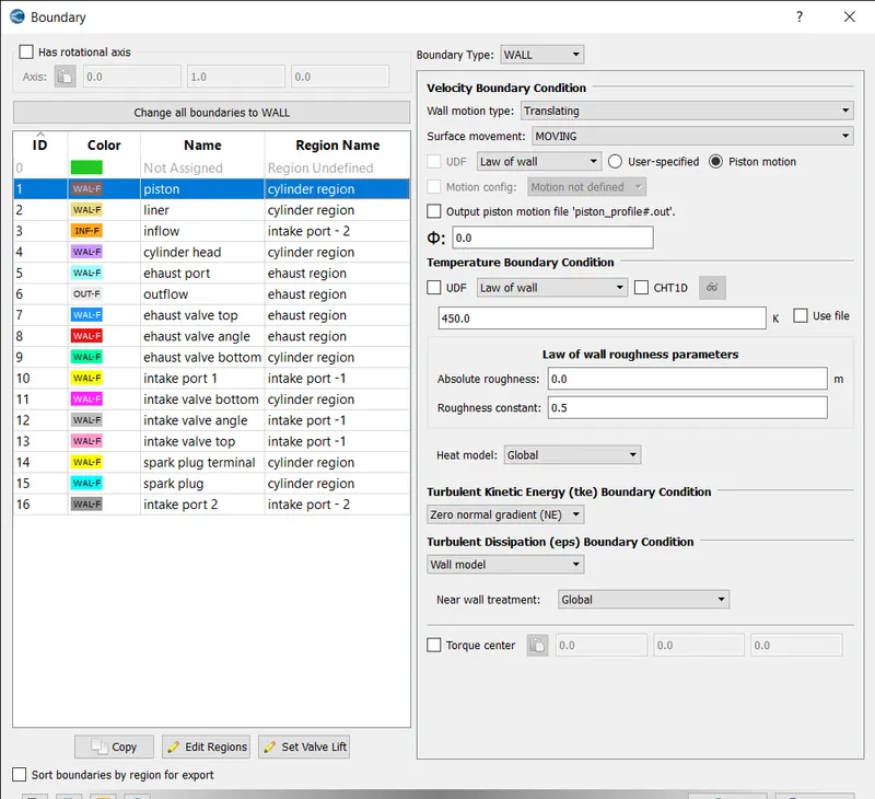
The boundary type is set to wall and motion as translating and movement as moving and temperature b.c. law of wall of 450k is assigned.
LINER:
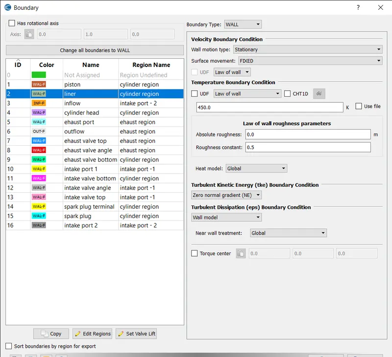
The boundary type is set to wall and motion as stationary and movement as fixed and temperature b.c. law of wall of 450k is assigned.
INFLOW:
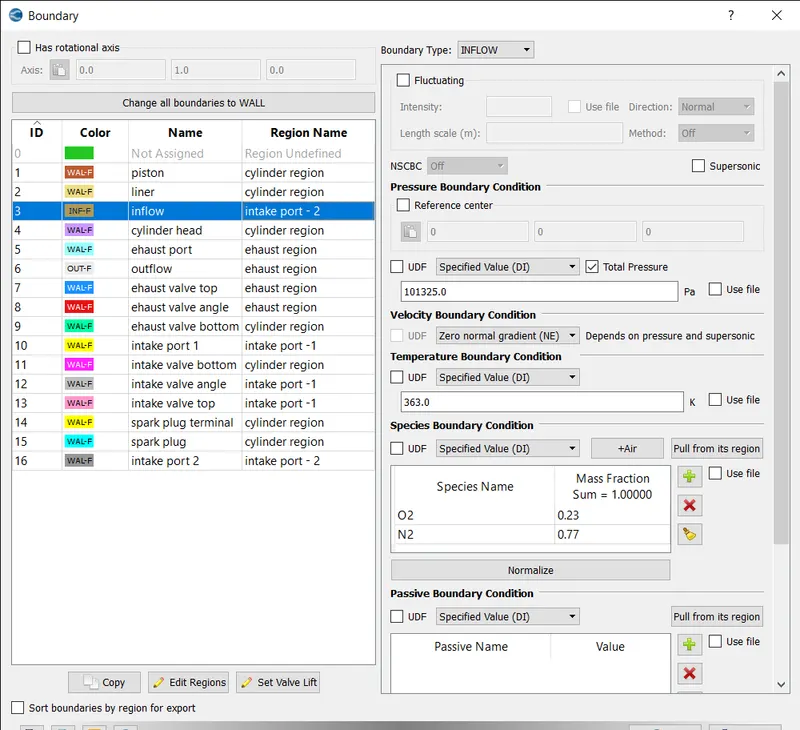
The boundary type is set to inflow and pressure b.c as 101325pa and temperature b.c. as 363k and air is added as species.
CYLINDER HEAD:
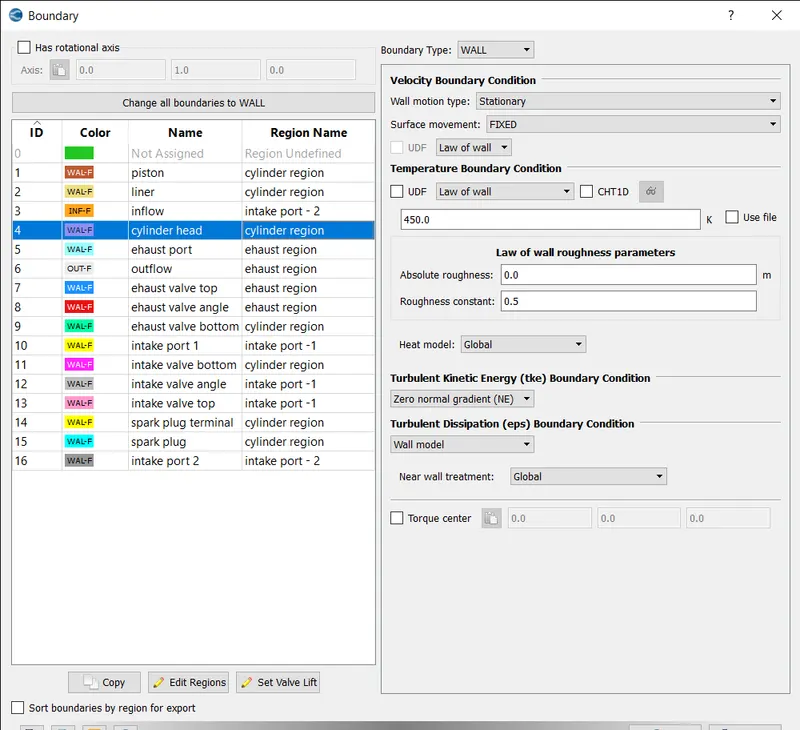
The boundary type is set to wall and motion as stationary and movement as fixed and temperature b.c. law of wall of 450k is assigned.
EXHAUST PORT:
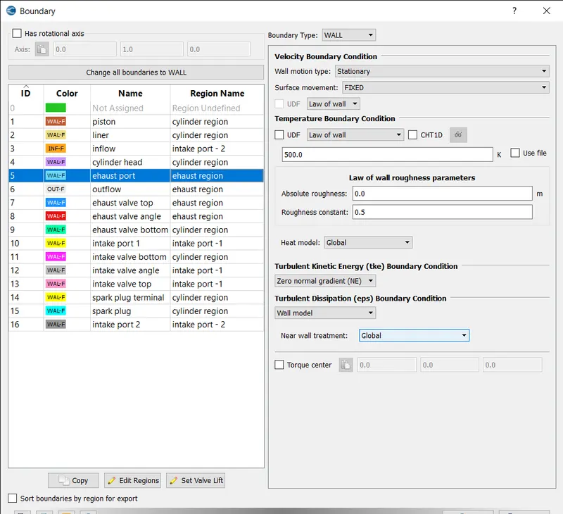
The boundary type is set to wall and motion as stationary and movement as fixed and temperature b.c. law of wall of 500k is assigned.
OUTFLOW:
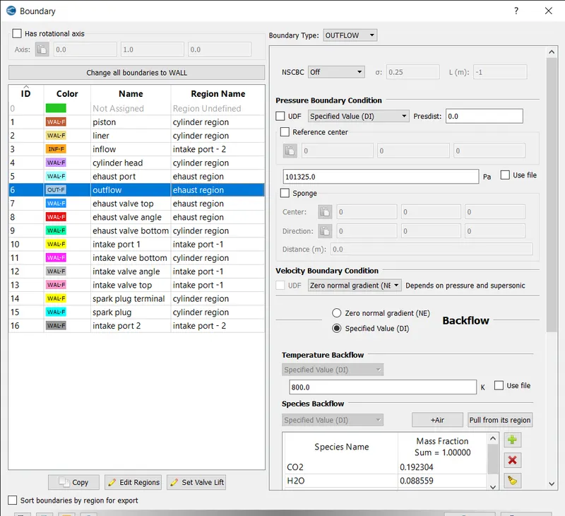
The boundary type is set to outflow and pressure b.c. as atm pressure and temperature b.c. law of wall of 800k is assigned and species backflow is pulled from its region.
EXHAUST VALVE TOP:
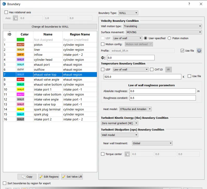
The boundary type is set to wall and motion as translating and movement as moving and temperature b.c. law of wall of 525k is assigned. For profile the exhaust_lift.in file is imported.
EXHAUST VALVE ANGLE:
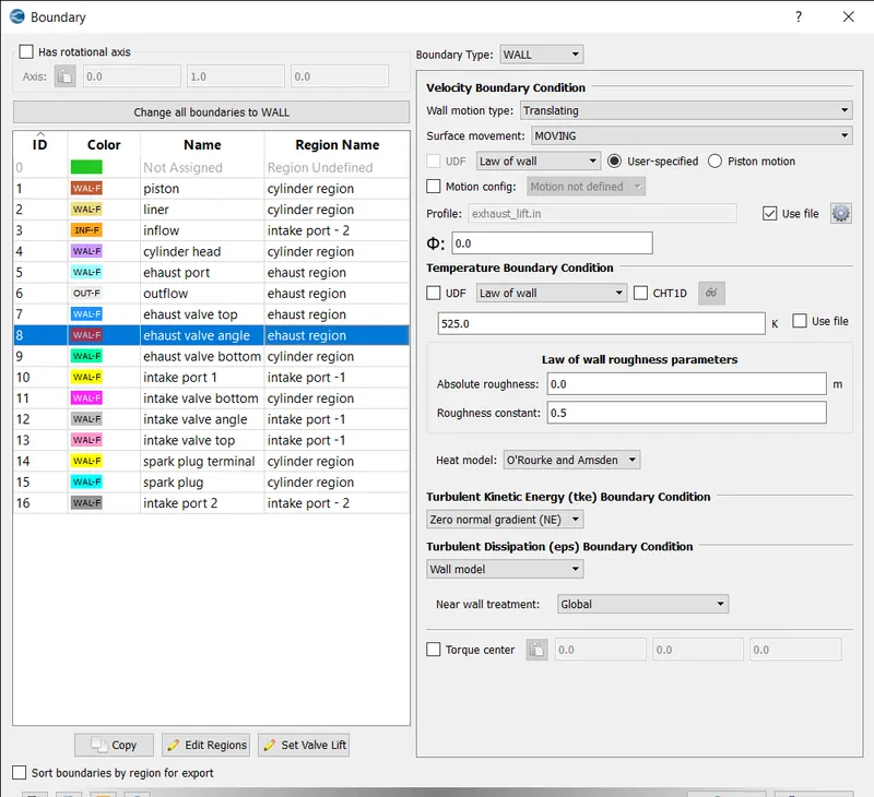
The boundary type is set to wall and motion as translating and movement as moving and temperature b.c. law of wall of 525k is assigned. For profile the exhaust_lift.in file is imported.
EXHAUST VALVE BOTTOM:
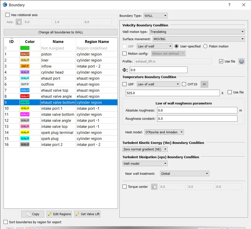
The boundary type is set to wall and motion as translating and movement as moving and temperature b.c. law of wall of 525k is assigned. For profile the exhaust_lift.in file is imported.
INTAKE PORT 1:
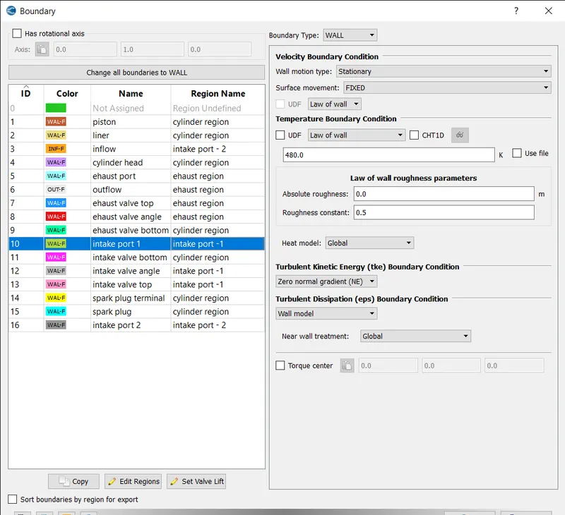
The boundary type is set to wall and stationary as translating and movement as fixed and temperature b.c. law of wall of 480k is assigned.
INTAKE VALVE BOTTOM:
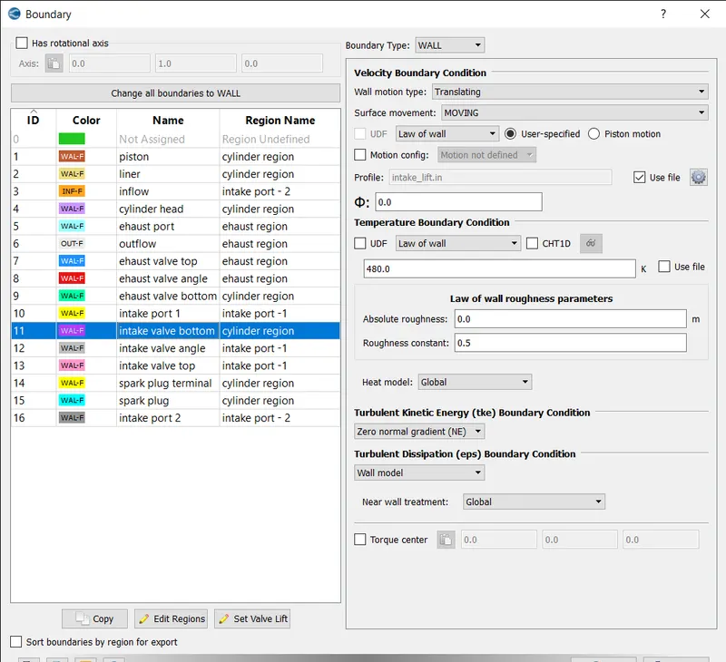
The boundary type is set to wall and motion as translating and movement as moving and temperature b.c. law of wall of 480k is assigned. For profile the intake_lift.in file is imported.
INTAKE VALVE ANGLE:
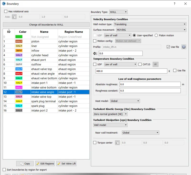
The boundary type is set to wall and motion as translating and movement as moving and temperature b.c. law of wall of 480k is assigned. For profile the intake_lift.in file is imported.
INTAKE VALVE TOP:
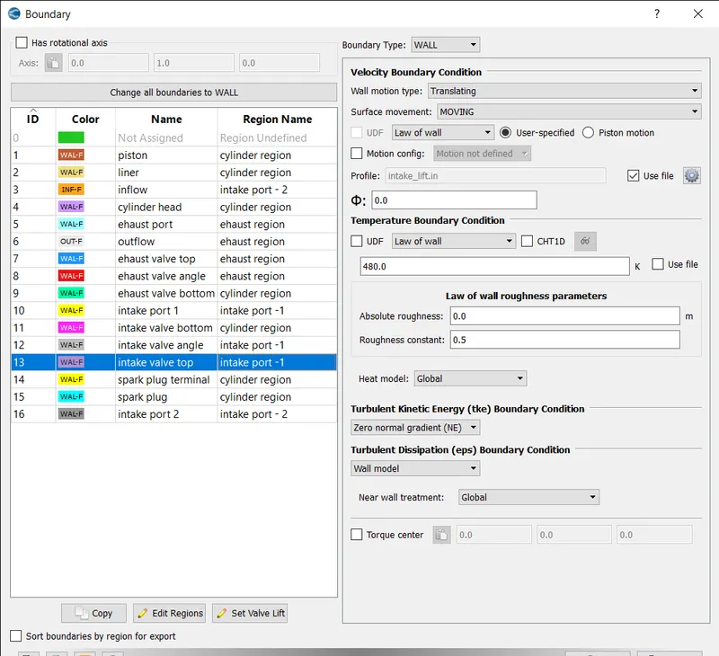
The boundary type is set to wall and motion as translating and movement as moving and temperature b.c. law of wall of 480k is assigned. For profile the intake_lift.in file is imported.
SPARK PLUG TERMINAL:
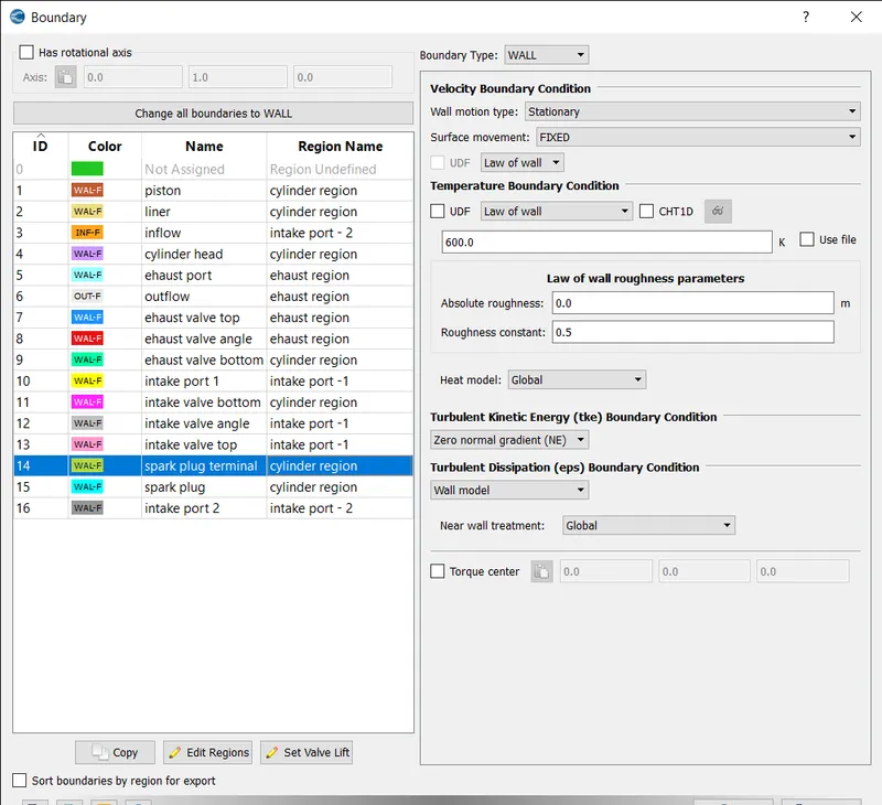
The boundary type is set to wall and motion as stationary and movement as fixed and temperature b.c. law of wall of 600k is assigned.
SPARK PLUG:
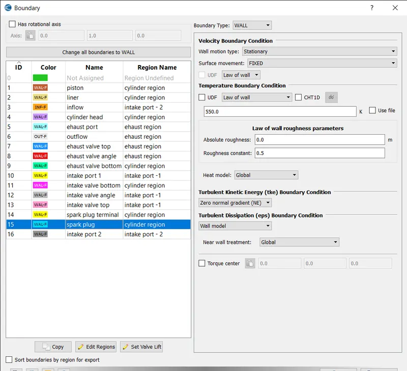
The boundary type is set to wall and motion as stationary and movement as fixed and temperature b.c. law of wall of 550k is assigned.
INTAKE PORT 2:
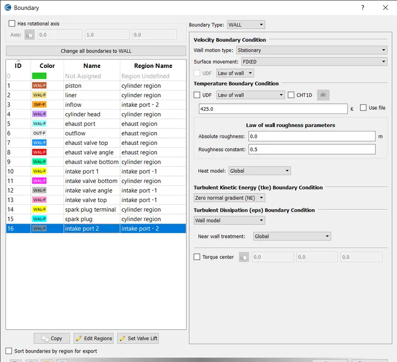
The boundary type is set to wall and motion as stationary and movement as fixed and temperature b.c. law of wall of 425k is assigned.
- EVENTS:
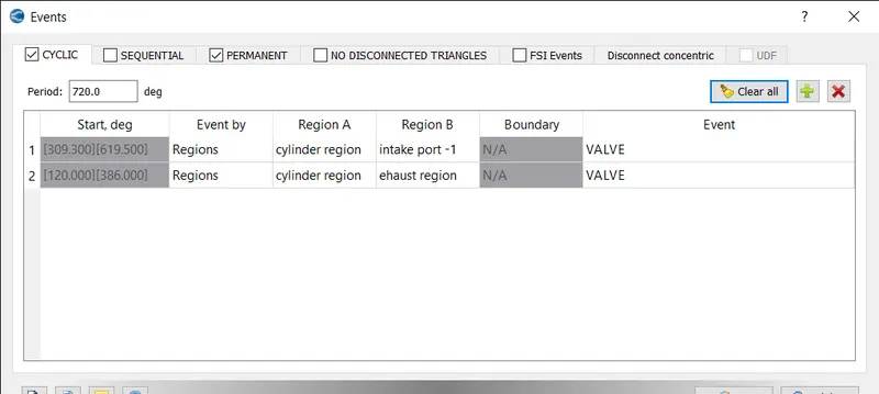
CYCLIC EVENT:
The cyclic event is created between cylinder region and intake port 1 and exhaust region and assigned the event as valve.
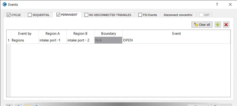
PERMANENT EVENT:
The permanent event is created between intake port 1 and intake port 2 and keep the event as open.
After turning on the events flag, the event can be set by selecting the events option in the case set-up tree.
Events can be cyclic, permanent or sequential.
Based on how the event should occur, the type of event can be chosen from the options available.
The event can repeat itself over cycles, in a sequence or can be set permanently. Based on this setting, Converge creates what is called as disconnected triangles. These are triangles that Converge creates and do not show up in post processing as they are temporarily created for the purpose of simulating the event.
Triangles are created for when there should be no interaction between the 2 regions and these triangles are deactivated when there is supposed to be an interaction between the 2 regions. It is important to note that no triangles must be created by the user, only events must be defined in order to have no intersecting triangles.
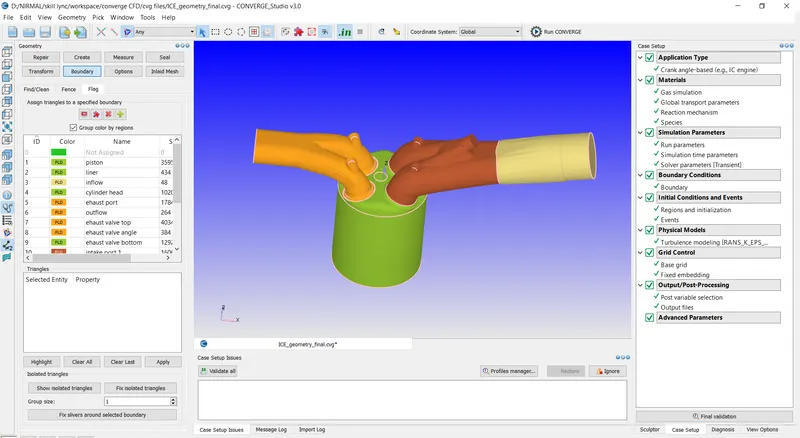
- GROUP COLOUR BY REGION:
when the group color by region is selected the model is grouped by regions.
- PHYSICAL MODEL:
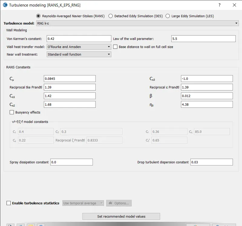
The RNG K-epsilon is selected for turbulence model and the values are kept default.
- GRID CONTROL:
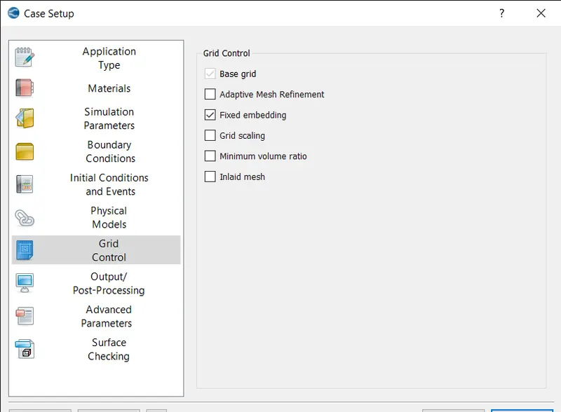
In grid control the fixed embedding is selected.
- BASE GRID:
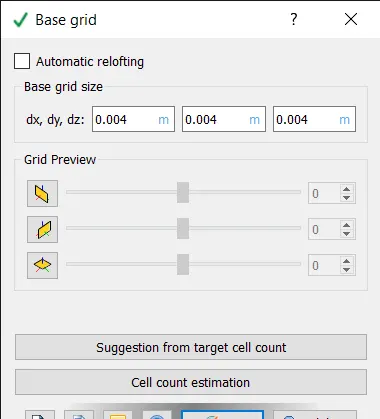
The base grids are defined as 0.004 m and press ok.
- FIXED EMBEDDING:
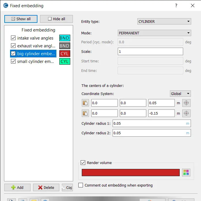
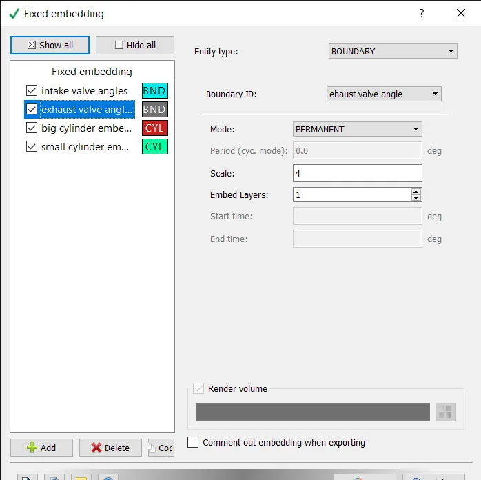
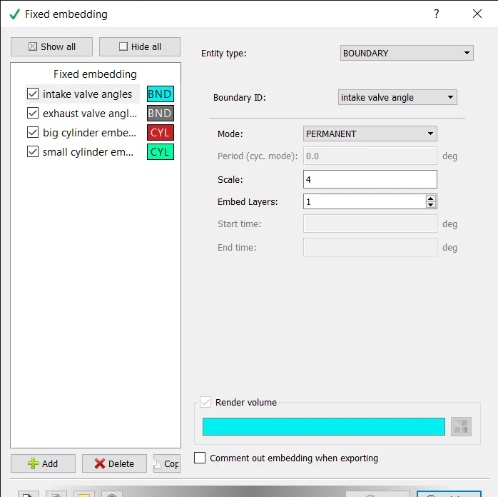
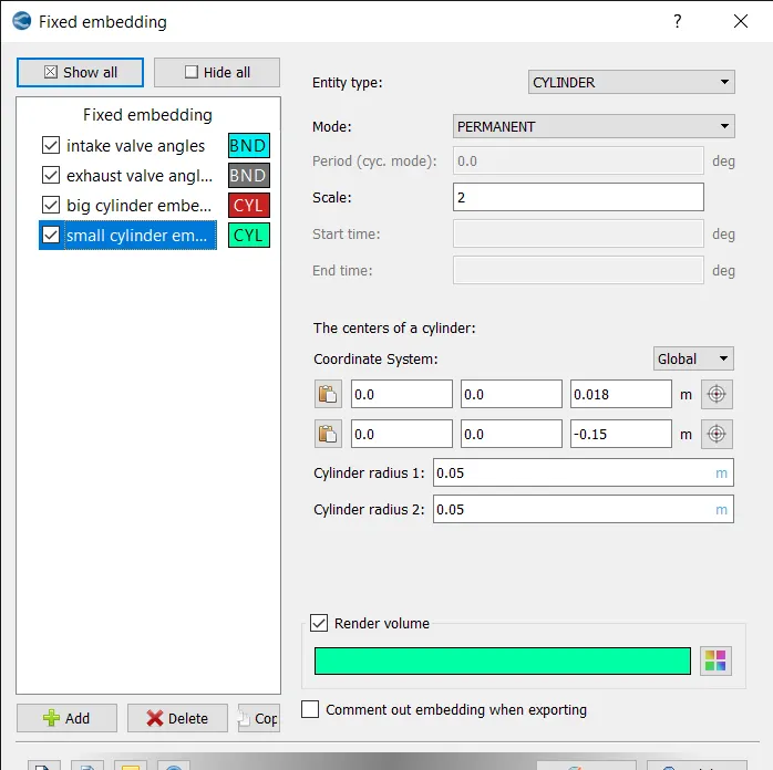
Fixed embedding is the feature which is used to add mesh to the required locations.
The fixed embedding is created for big cylinder, small cylinder, intake valve angles and exhaust valve angles.
BIG CYLINDER EMBEDDING:
EXHAUST VALVE ANGLE EMBEDDING:
INTAKE VALVE ANGLE EMBEDDING:
SMALL CYLINDER EMBEDDING:
- POST VARIABLE SELECTION:
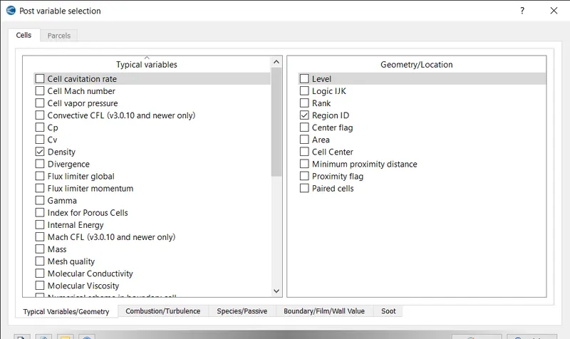
Keep the default values in typical variables tab.
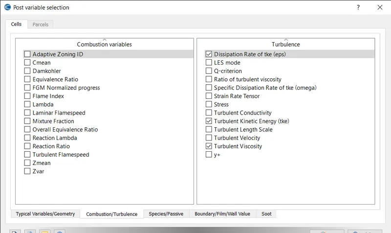
Under combustion/turbulence the values are kept default.
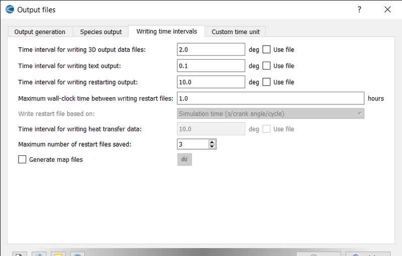
- OUTPUT FILES:
The interval for writing 3d output data files and restarting outputs are defined.
- Exporting the input files to a folder
- Then the executable is pasted inside the folder
- The simulation is run in Cygwin.
- The simulation is run as coarse by changing the grid scale as -2.
- The postconvert executable is pasted in the output folder.
- The post conversion is done on Cygwin and converted into the type that paraview reads.
- The results are then post processed using paraview.
RESULTS:
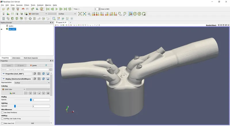
GEOMETRY:
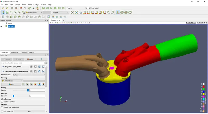
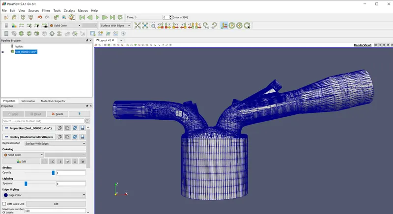
GEOMETRY WITH MESH:
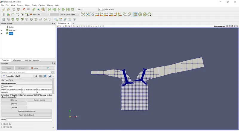
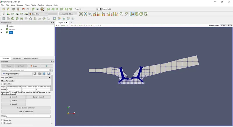
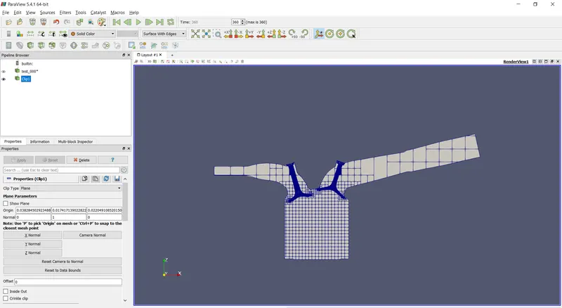
MESH AT DIFFERENT TIME STEP:
The below images show the mesh variation at different time step.
0:
50:
100:
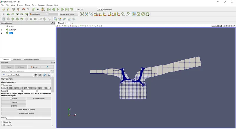
150:
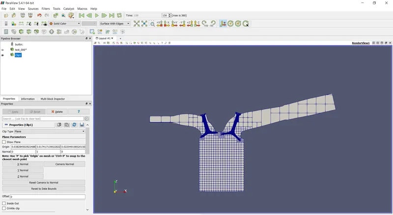
200:
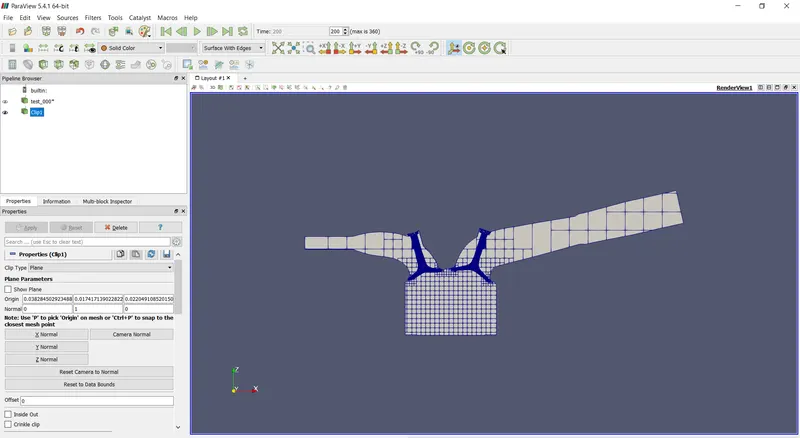
250:
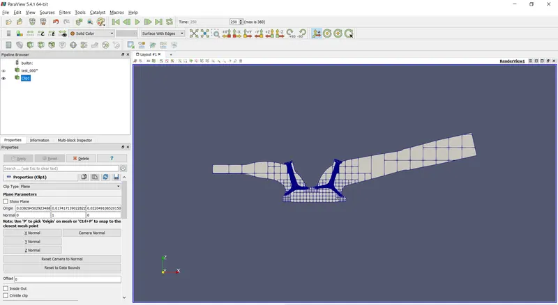
300:
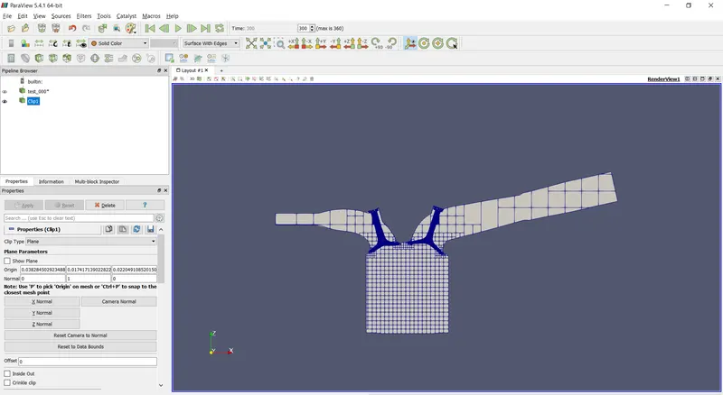
360:
MESH ANIMATION:
https://drive.google.com/file/d/1CF2cy1-7Lr_ow0-rXchKVYFd7xOXt4hv/view?usp=sharing
The above animation shows how the mesh varies with respect to time.
ANIMATION OF WORKING OF PFI:
https://drive.google.com/file/d/1RzvS2m6lKwEnt7cIWApLJpGInPJfHjFm/view?usp=sharing
https://drive.google.com/file/d/1IKooorrbxsOAehcGKlv2PUNxlAkTR0Gg/view?usp=sharing
The above two animation shows the working of valves and piston of port fuel injection.