Project 2 - Rankine cycle Simulator
AIM:
- To simulate a rankine cycle using MATLAB.
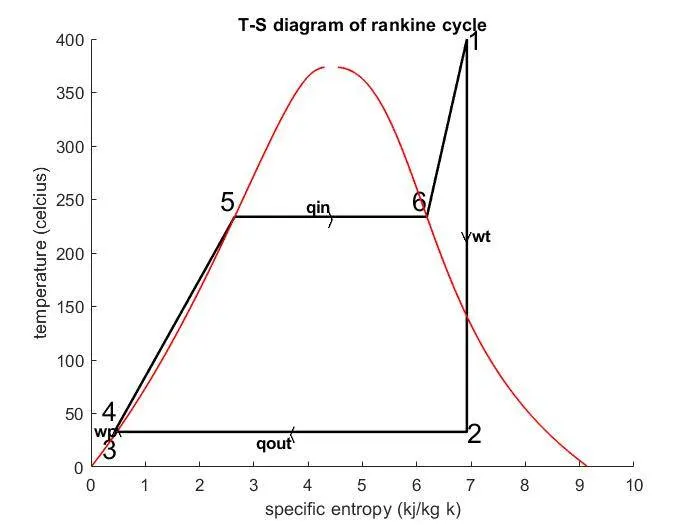
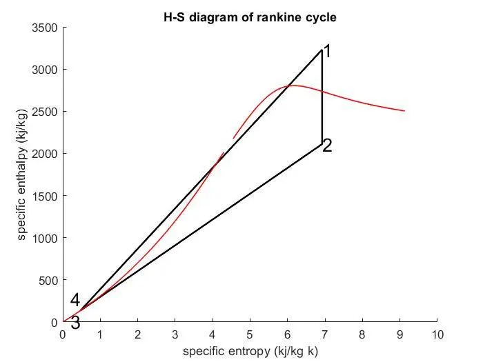
- To plot T-S and H-S diagram of rankine cycle.
- To find net work output and back work ratio for the given inputs.
THEORY:
The Rankine cycle is a model used to predict the performance of steam turbine systems. It was also used to study the performance of reciprocating steam engines. The Rankine cycle is an idealized thermodynamic cycle of a heat engine that converts heat into mechanical work while undergoing phase change.
FOUR PROCESS IN RANKINE CYCLE:
There are four processes in the Rankine cycle. The states are identified by numbers in the T-S diagram.
- Process 1–2: The working fluid is pumped from low to high pressure. As the fluid is a liquid at this stage the pump requires little input energy.
In other words Process 1-2 is [Isentropic compression]
- Process 2–3: The high-pressure liquid enters a boiler, where it is heated at constant pressure by an external heat source to become a dry saturated vapour. The input energy required can be easily calculated graphically, using an h-s chart, or numerically, using steam tables.
In other words Process 2-3 is [Constant pressure heat addition in boiler]
- Process 3–4: The dry saturated vapour expands through a turbine, generating power. This decreases the temperature and pressure of the vapour, and some condensation may occur. The output in this process can be easily calculated using the chart or tables noted above.
In other words Process 3-4 is [Isentropic expansion]
- Process 4–1: The wet vapour then enters a condenser, where it is condensed at a constant pressure to become a saturated liquid.
In other words Process 4-1 is [Constant pressure heat rejection in condenser]
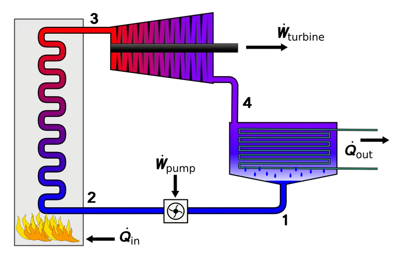
SIMPLE RANKINE CYCLE
FORMULAS USED:
- HEAT SUPPLIED:
Qin = h1-h4,
- HEAT REJECTED:
Qout = h2-h3,
- WORKDONE BY TURBINE:
wturbine = h1-h2,
- WORKDONE BY PUMP:
wpump = h4-h3,
- NET WORKDONE:
Wnet = wturbine - wpump,
- EFFICIENCY:
Efficiency = Wnet/ Qin ,
- SPECIFIC STEAM CONSUMPTION:
Ssc = 3600/ Wnet ,
- BACK WORK RATIO:
Back work ratio = wpump/wturbine.
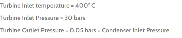
INPUTS USED:
MATLAB CODE:
clear all
close all
clc

disp('RANKINE CYCLE SIMULATOR')
disp('Process 1-2 : Reversible adiabatic expansion in the turbine')
disp('Process 2-3 : Constant-pressure transfer of heat in the condenser')
disp('Process 3-4 : Reversible adiabatic pumping process in the feed pump')
disp('Process 4-1 : Constant-pressure transfer of heat in the boiler')
fprintf('\n')

%inputs
disp('INPUTS')
p1=input('Enter the pressure at the inlet of turbine(bar)= ');
t1=input('Enter the temperature at the inlet of turbine(c)= ');
p2=input('Enter the pressure at the inlet of condenser(bar)= ');

%steam condition at inlet of turbine (state 1)
h1=XSteam('h_pt',p1,t1);
s1=XSteam('s_pt',p1,t1);

%steam condition at inlet of condenser (state 2)
s2=s1;
sf2=XSteam('sL_p',p2);
sg2=XSteam('sV_p',p2);
x2=(s2-sf2)/(sg2-sf2);

hg2=XSteam('hV_p',p2);
hf2=XSteam('hL_p',p2);
h2=hf2+x2*(hg2-hf2);

t2=XSteam('Tsat_p',p2);

%steam condition at outlet of condenser (state 3)
p3=p2;
x3=0;

hf3=XSteam('hL_p',p3);
hg3=XSteam('hV_p',p3);
h3=hf3+x3*(hg3-hf3);

sf3=XSteam('sL_p',p3);
sg3=XSteam('sV_p',p3);
s3=sf3+x3*(sg3-sf3);

vf3=XSteam('vL_p',p3);

t3=XSteam('Tsat_p',p3);

%steam condition at outlet of pump (state 4)
p4=p1;
s4=s3;

h4=h3+vf3*(p4-p3);

cp4=XSteam('Cp_ps',p4,s4);
cv4=XSteam('Cv_ps',p4,s4);
lambda=cp4/cv4;
r=(lambda-1)/lambda;
t4=t3*((p4/p3)^r);

%point 5
t5=XSteam('Tsat_p',p1);
s5=XSteam('sL_p',p1);

%point6
t6=t5;
s6=XSteam('sV_p',p1);

%heat supplied
qin = h1-h4;

%workdone by turbine
w_t = h1-h2;

%heat rejected
qout = h2-h3;

%workdone by feed pump
w_p = (h4-h3)*100;

%net workdone
w_net=w_t-w_p;

%efficiency of rankine cycle
eff_rankine = (w_net/qin)*100;

%specific steam consumption
ssc=3600/w_net;

%back work ratio
back_work_ratio=w_p/w_t;

%calculation for plotting for liquid and vapour lines
temp=linspace(1,400,1000);
for i=1:length(temp)
    H_L(i)=XSteam('hL_T',temp(i));
    H_V(i)=XSteam('hV_T',temp(i));
    S_L(i)=XSteam('sL_T',temp(i));
    S_V(i)=XSteam('sV_T',temp(i));
end

%results
fprintf('\n')
fprintf('RESULTS\n')
fprintf('At state point 1:\n')
fprintf('P1 is :%f Bar\n',p1)
fprintf('T1 is :%f celcius\n',t1)
fprintf('H1 is :%f kj/kg\n',h1)
fprintf('S1 is :%f kj/kgk\n\n',s1)

fprintf('At state point 2:\n')
fprintf('P2 is :%f Bar\n',p2)
fprintf('T2 is :%f celcius\n',t2)
fprintf('H2 is :%f kj/kg\n',h2)
fprintf('S2 is :%f kj/kgk\n',s2)
fprintf('X2 is :%f \n\n',x2)

fprintf('At state point 3:\n')
fprintf('P3 is :%f Bar\n',p3)
fprintf('T3 is :%f celcius\n',t3)
fprintf('H3 is :%f kj/kg\n',h3)
fprintf('S3 is :%f kj/kgk\n\n',s3)

fprintf('At state point 4:\n')
fprintf('P4 is :%f Bar\n',p4)
fprintf('T4 is :%f celcius\n',t4)
fprintf('H4 is :%f kj/kg\n',h4)
fprintf('S4 is :%f kj/kgk\n\n',s4)

%workdone by  turbine
fprintf('wt is : %f kj/kg\n',w_t)

%workdone by pump
fprintf('wp is : %f kj/kg\n',w_p)

%net workdone
fprintf('Wnet is : %f kj/kg\n',w_net)

%thermal efficiency
fprintf('Efficiency : %f percent\n',eff_rankine)

%specific fuel consumption
fprintf('ssc is : %f kg/kwh\n',ssc)

%back work ratio
fprintf('Back work ratio : %f\n',back_work_ratio)

%plotting t-s diagram
figure(1)
hold on

%plotting lines of all states
plot([s1 s2 s3 s4 s5 s6 s1],[t1 t2 t3 t4 t5 t6 t1],'linewidth',1.5,'color','k')

%marking end points
text(s1,t1,'1','fontsize',16,'horizontalalignment','left');
text(s2,t2,'2','fontsize',16,'horizontalalignment','left');
text(s3,t3,'3','fontsize',16,'horizontalalignment','right','verticalalignment','top');
text(s4,t4,'4','fontsize',16,'horizontalalignment','right','verticalalignment','bottom');
text(s5,t5,'5','fontsize',16,'horizontalalignment','right','verticalalignment','bottom');
text(s6,t6,'6','fontsize',16,'horizontalalignment','right','verticalalignment','bottom');

%plotting liquid and vapour lines
plot(S_L,temp,'linewidth',1,'color','r')
plot(S_V,temp,'linewidth',1,'color','r')

%marking direction and notations
text(s1,(t1+t2)/2,'\bf\vee','horizontalalignment','center','color','k')
text(s1,(t1+t2)/2,'\bf wt','horizontalalignment','left','color','k')
text((s2+s3)/2,t2,'\bf\langle','horizontalalignment','center','color','k')
text((s2+s3)/2,t2,'\bf qout','horizontalalignment','right','verticalalignment','top','color','k')
text(s3,(t3+t4)/2,'\bf\wedge','horizontalalignment','center','color','k')
text(s3,(t3+t4)/2,'\bf wp','horizontalalignment','right','color','k')
text((s5+s6)/2,t5,'\bf\rangle','horizontalalignment','center','color','k')
text((s5+s6)/2,t5,'\bf qin','horizontalalignment','right','verticalalignment','bottom','color','k')

xlabel('specific entropy (kj/kg k)')
ylabel('temperature (celcius)')
title('T-S diagram of rankine cycle')

%plotting H-S diagram
figure(2)
hold on

%plotting lines of all process
plot([s1 s2 s3 s4 s1],[h1 h2 h3 h4 h1],'linewidth',1.5,'color','k')

%marking end points
text(s1,h1,'1','fontsize',16,'horizontalalignment','left')
text(s2,h2,'2','fontsize',16,'horizontalalignment','left')
text(s3,h3,'3','fontsize',16,'horizontalalignment','right','verticalalignment','top')
text(s4,h4,'4','fontsize',16,'horizontalalignment','right','verticalalignment','bottom')

%plotting liquid and vapour lines
plot(S_L,H_L,'linewidth',1,'color','r')
plot(S_V,H_V,'linewidth',1,'color','r')

xlabel('specific entropy (kj/kg k)')
ylabel('specific enthalpy (kj/kg)')
title('H-S diagram of rankine cycle')
MATLAB CODE EXPLANATION:
- XSteam data is used to extract steam and water properties of enthalpy entropy at specific pressure and temperatures for saturated liquid and vapour condition.
- The program requires the input of pressure and temperature at state point 1 and pressure at state 2.
- With help of these inputs and XSteam data all the state points of the cycle are calculated.
- Further state points are calculated by using thermodynamic relations and by extracting from XSteam data.
- The net work done , workdone by turbine, workdone by pump, heat in, heat out are calculated.
- Efficiency, specific steam consumption (ssc) and back work ratio is calculated.
- Plot of T-S and H-S diagram is created from all the points obtained from the program.
- The results are displayed in the command window.
OUTPUT:
T-S DIAGRAM:
H-S DIAGRAM:
RESULTS:
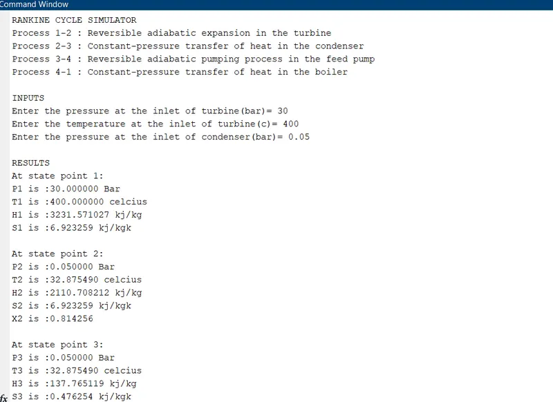
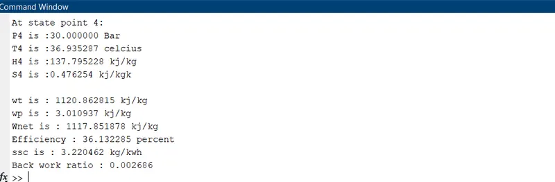
CONCLUSION:
Thus the rankine cycle is simulated using MATLAB.
REFERENCES: