Week 9: Project 1 - Surface preparation and Boundary Flagging (PFI)
Surface preparation and Boundary Flagging of a Port Fuel Injection engine(PFI)
In this project, we will prepare the surface of a PFI engine by cleaning the given CAD file and marking the boundaries followed by which we shall simulate a no hydro simulation in converge and postprocessing in paraview.
PFI-a look
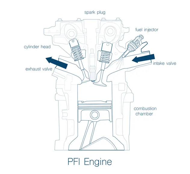
PFI engines use a three-way catalytic converter, exhaust sensors and computer-controlled engine management to constantly adjust the fuel-to-air ratio injected into each cylinder. Since the fuel is injected right before the cylinder, most of the fuel will be drawn into the cylinder causing less collection/stagnation of fuel in the manifold. One other advantage of this type of injection is that, the intake manifolds is not necessary to be made of metal as intake will mostly contain air at atmospheric pressure. This can reduce the weight and overall cost of the engine as well.
Procedure
- The first step involves importing the geometry (.stl file provided to you) and cleaning the geometry, marking the boundaries and then patching the geometry. The resultant geometry is shown below:
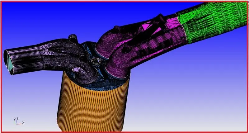
- The individual boundaries that are flagged are shown below:
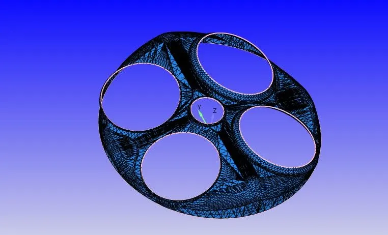
- Cylinder Head
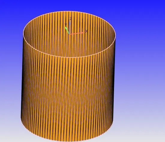
- Liner
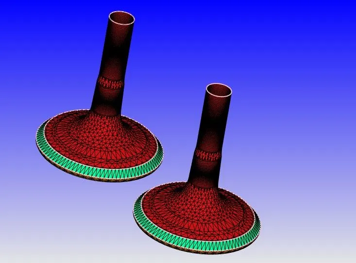
- Exhaust valve
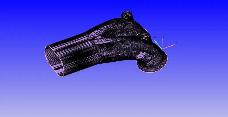
- Exhaust Port
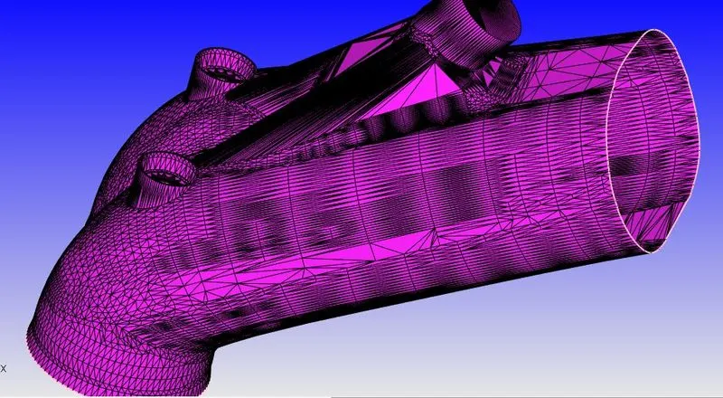
- Intake Port
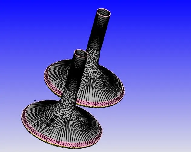
- Intake Valve
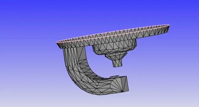
- Spark plug
Once done, lets begin case setup:
- Set the application type as IC engine based.
- In the materials, choose the reaction mechanism and turn it on.
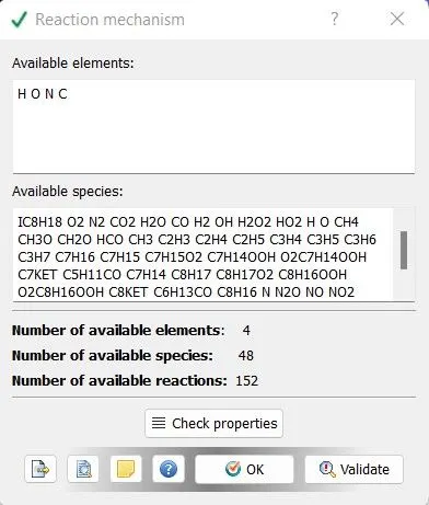
- Import the necessary ".dat" file and click OK.
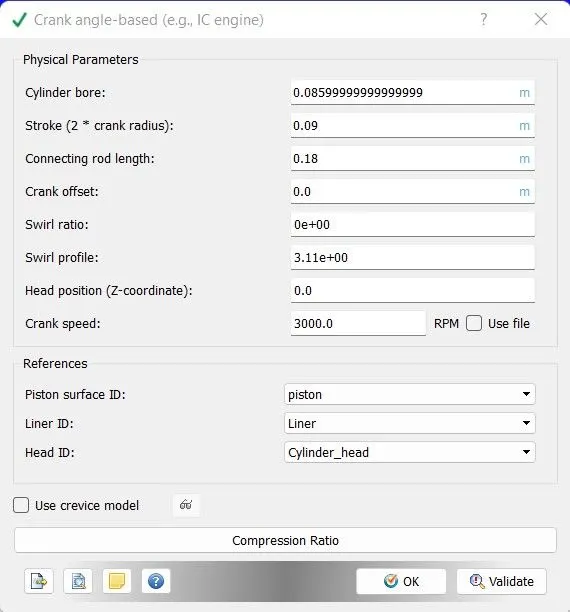
- Enter these parameters as shown above for a crank case engine.
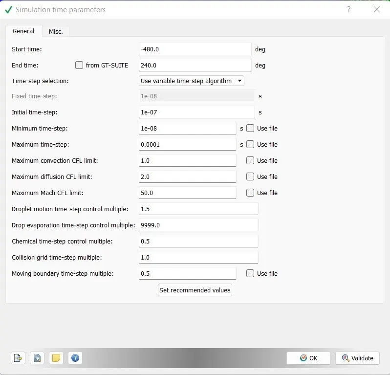
- Enter the time parameters to run the simulation as shown above.
- Once done, create four regions that depict different physical and chemical properties of the flow at different regions as cylinder, intake regions-1 &2 and exhaust region as shown below.
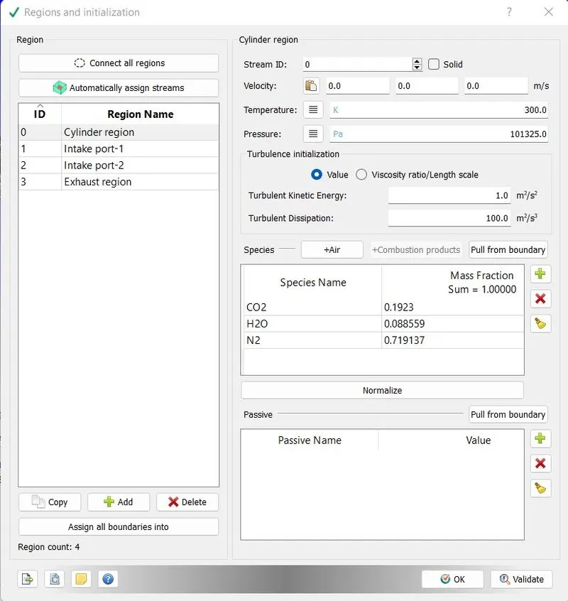
- The intake port-1 is the region closer to the cylinder and thus carries a fuel `C_8H_18`with air as follows`
-
Species Mass fraction `C_8H_18` 0.025508 `O_2` 0.20157 `N_2` 0.77292 - The intake port 2 contains only air and hence the air is entered
- The exhaust and the cylinder regions contains the products of combustion viz. `CO_2,H_2O,N_2`with the mass fractions which are specified below:
-
Species Mass fraction `CO_2` 0.1923 `H_2O` 0.08559 `N_2` 0.719137 - The temperatures are setup accordingly.
- Once done, click on boundary and allot "law of wall" to the boundaries that were alloted the wall BC and for piston,mark the BC as wall with translation motion enabling a piston type motion.
- For intake valve and exhaust valve, import "intake_lift.in" and "exhaust_lift.in" files respectively.
- Once done,create events as shown below:
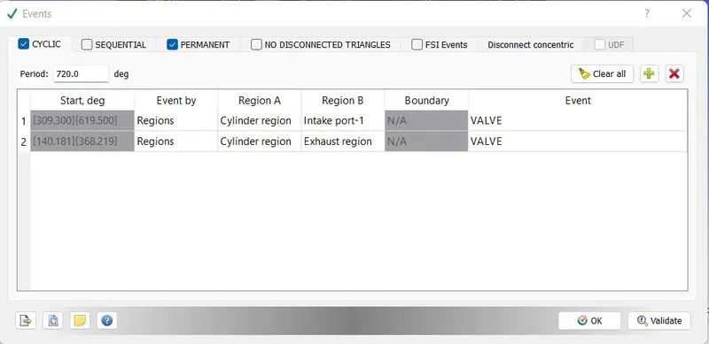
- A cyclic event is setup to simulate valve motion between cylinder regions and intake port-1
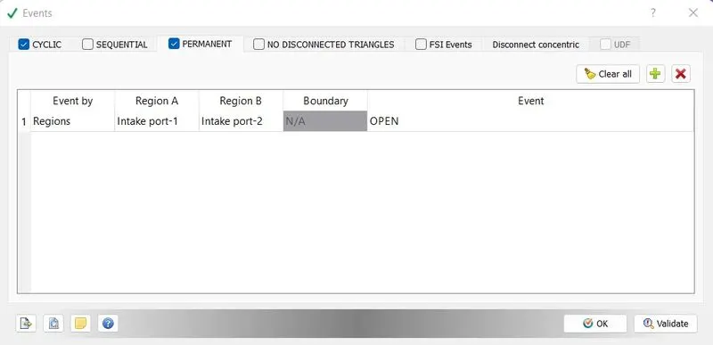
- A permanent event is setup between intake port-1 and intake port-2
- Once events are setup, base grid mesh size is specified and the files are exported to a folder and run in cygwin.
- Once done, the results are postprocessed in studio and viewed in paraview.
Animations
No hydro simulation of a PFI
Meshing view at different crank angles
Errors while cleaning the geometry
While importing the CAD file into the converge studio and running the diagnosis, we come across several types of errors namely:
Intersection errors: These errors occur when there are triangles which either intersect or pass through each other. To sort this out, delete intersecting triangles.
Open edge errors: These errors occur when there is a missing triangle between the components of the geometry. To sort this out, patch the places where we have gaps with triangles.
Non-Manifold errors:These errors occur when the edge of the triangle is shared between more than two triangles. To sort this out, we have to setup the case in such a way that Converge understands that this error is superficial.
Normal orientation errors: This error occurs when the normals of the triangles are not pointing into the fluid domain. To sort this out, reorient the normals facing towards the fluid region.
Thus the surface is prepared and the boundaries are flagged so that the geometry is ready for a full-scale combustion.