Week 9: Project 1 - Surface preparation and Boundary Flagging (PFI)
AIM
Surface preparation and Boundary Flagging (PFI)
OBJECTIVE
- Surface preparation and Boundary Flagging of PFI model
- Setup a no-hydro simulation
SURFACE PREPARATION
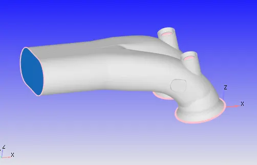
Import the PFI engine geometry into converge
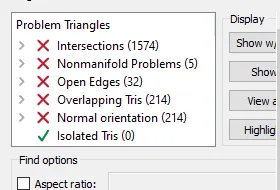
After running a diagnosis, some errors were found in the geometry
Intersections
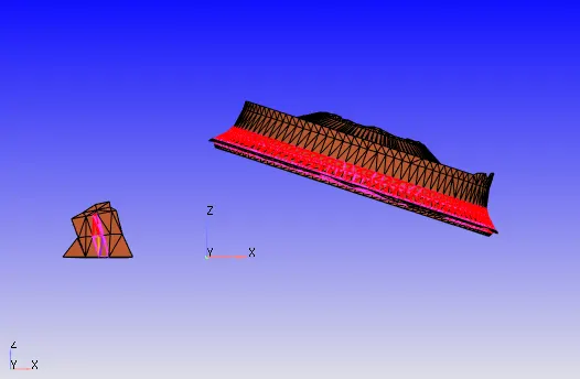
This error is caused by the intersection of triangles. This can be resolved by translation of the triangles. Here the triangles of the intake valve is intersecting with the triangles of the cylinder head. So, after boundary flagging the triangles of the intake valve is translated along the normal axis to avoid intersection.
Non-manifold problems
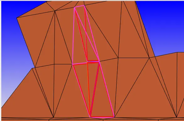
This error occurs when an edge is shared by more than two triangles. This can be resolved by deleting the wrongly created triangles.
Open edges
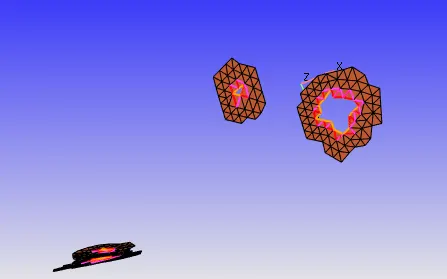
This error occurs when there are holes in the geometry. This can be resolved by patching.
Overlapping triangles
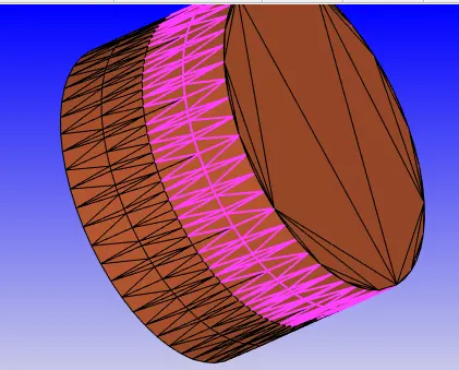
This error occurs when there are overlapping triangles in the geometry. This can be resolved by deleting one set of overlapping triangles.
Normal orientation
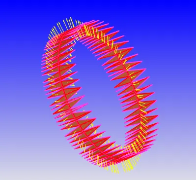
The normal of all the triangles should be pointing towards the fluid flow, otherwise this error occurs. So by changing the orientation of the triangles, this error can be fixed.
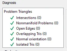
After fixing all the errors, run the diagnosis check again to confirm all errors are fixed.
BOUNDARY FLAGGING
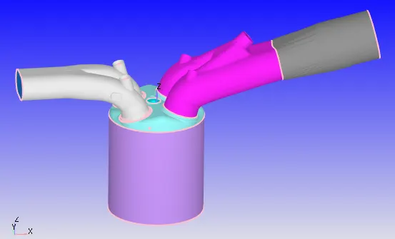
Piston, liner and cylinder head
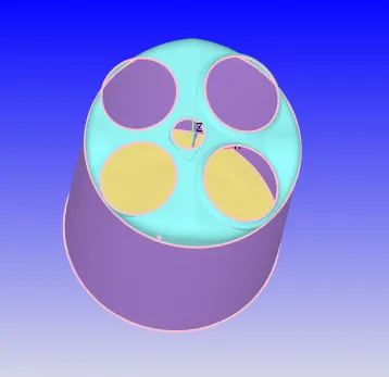
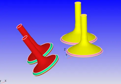
Intake and exhaust valves
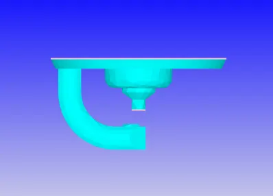
Spark plug
Intake port-1 and intake port-2
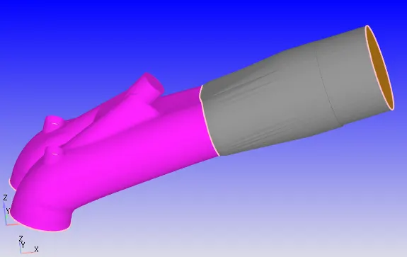
Exhaust port
No-hydro case setup
After surface preparation and boundary flagging, the next step is case setup.
In application type select crank angle based IC engine.
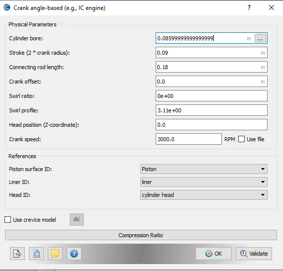
In crank angle based IC engine, enter the parameters of the engine.
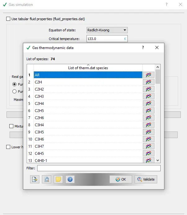
In gas simulation in the materials tab, upload therm.dat file in gas thermodynamic data
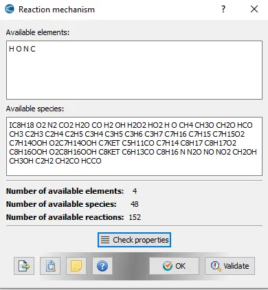
In Reaction mechanism, mech.dat file is uploaded.
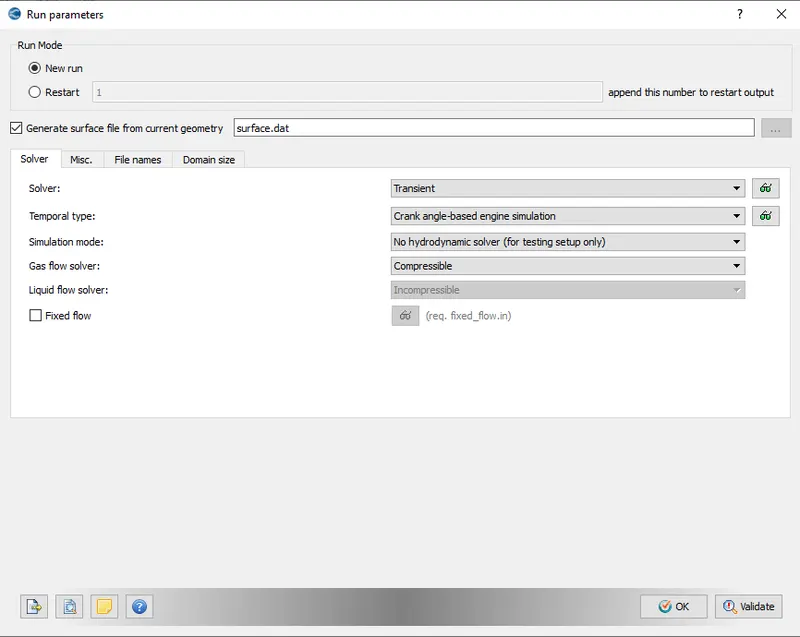
Run parameters
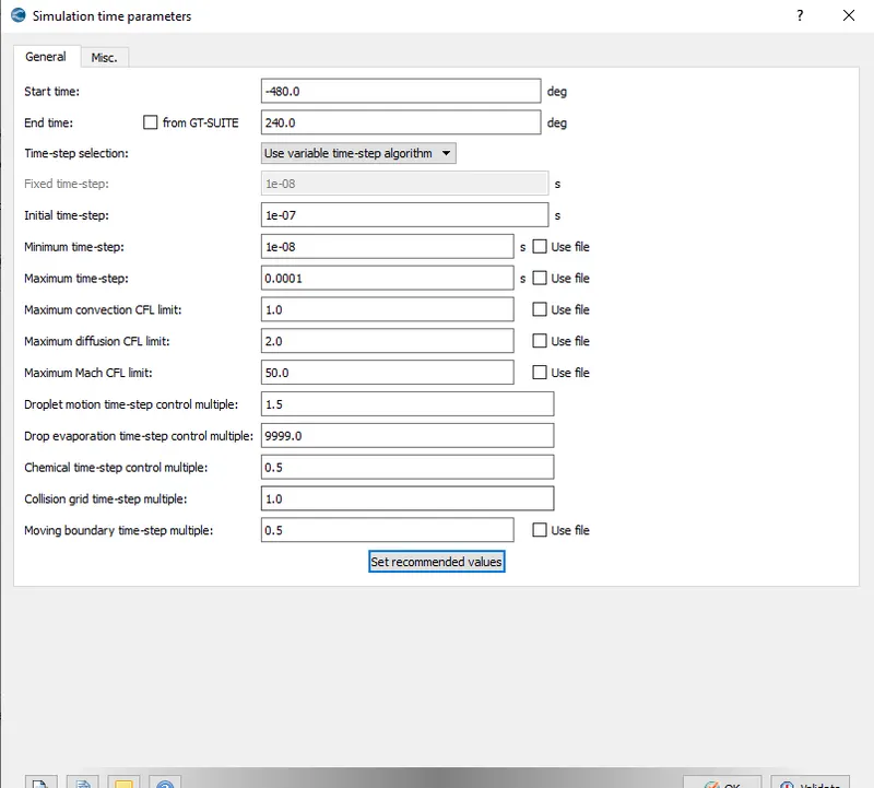
Simulation time parameters
In solver parameters default properties are maintained.
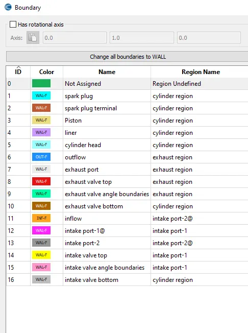
Boundary conditions
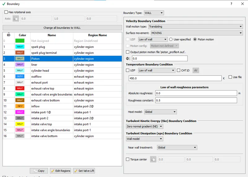
Piston
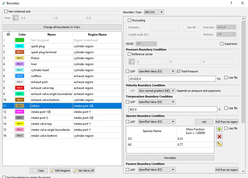
Inflow
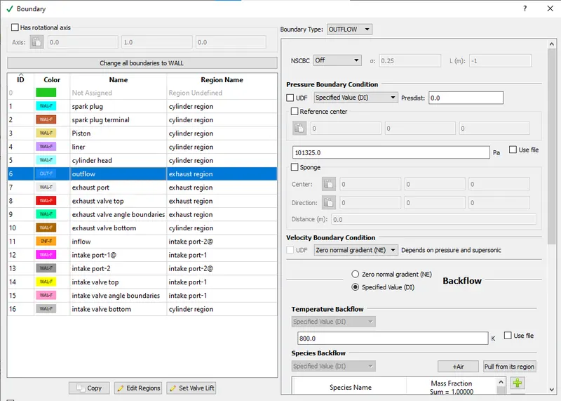
Outflow
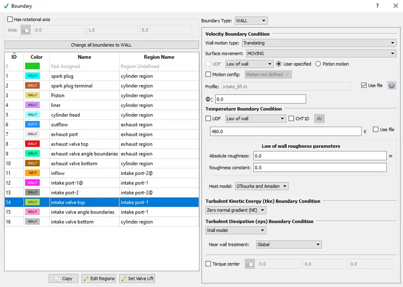
Intake valve top, angle and bottom
These three surfaces have exact same boundary conditions and valve motion is defined using a file 'intake_lift.in'.
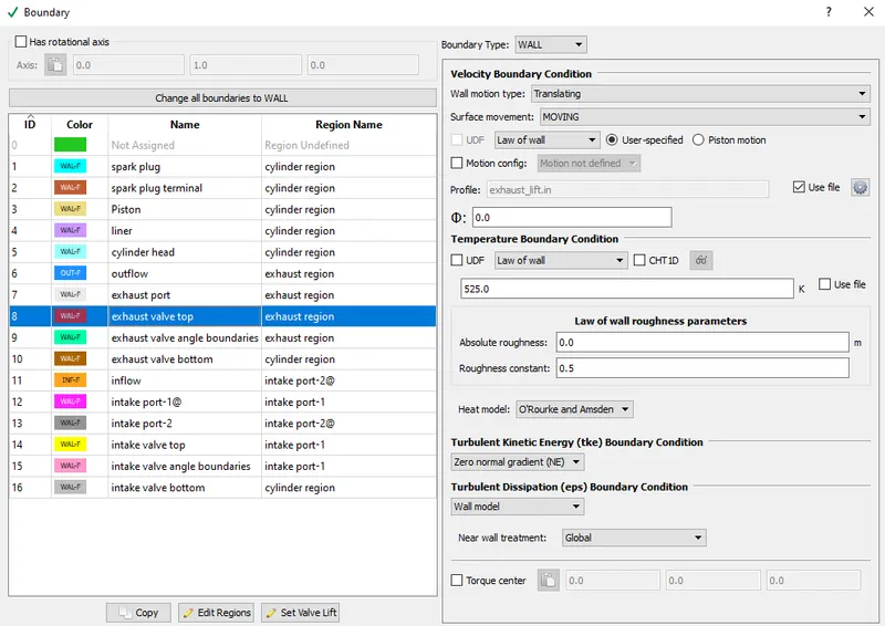
Exhaust valve top,angle and bottom
These three surfaces have exact same boundary conditions and valve motion is defined using a file 'exhaust_lift.in'.
All other boundaries are fixed wall boundaries. Only difference is in the temperature boundary condition.
cylinder head - 450K
liner - 450K
Spark plug - 550K
Spark plug electrode - 600K
Exhaust port - 500K
Intake port-1 and intake port-2 - 425K
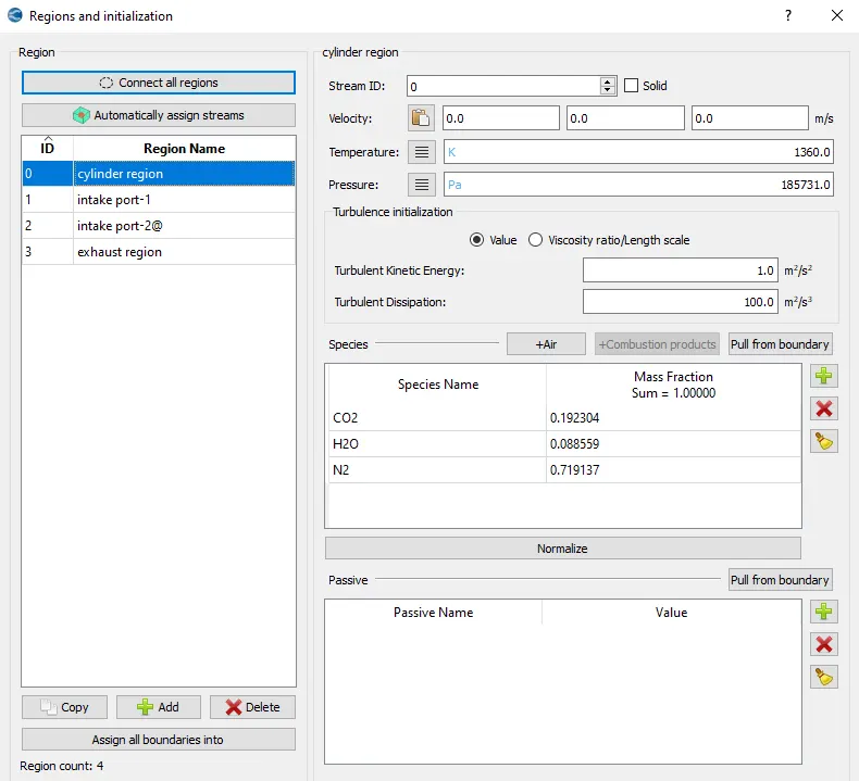
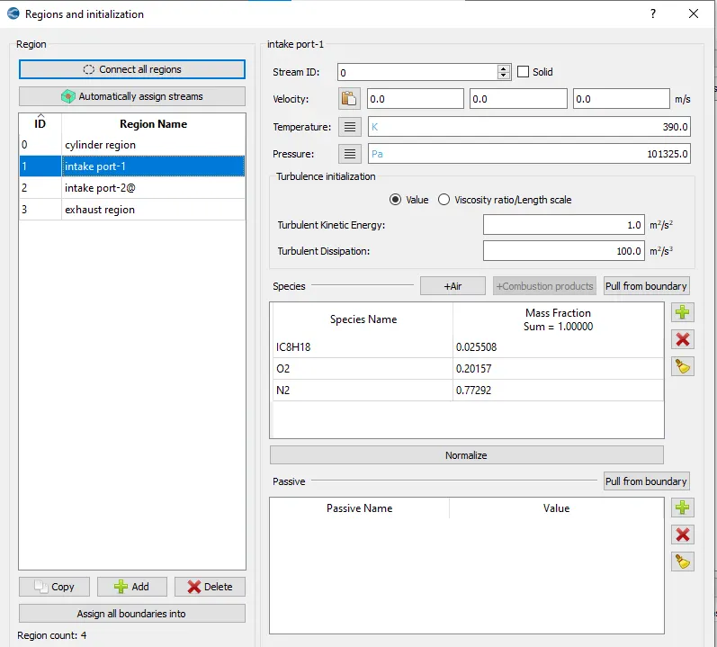
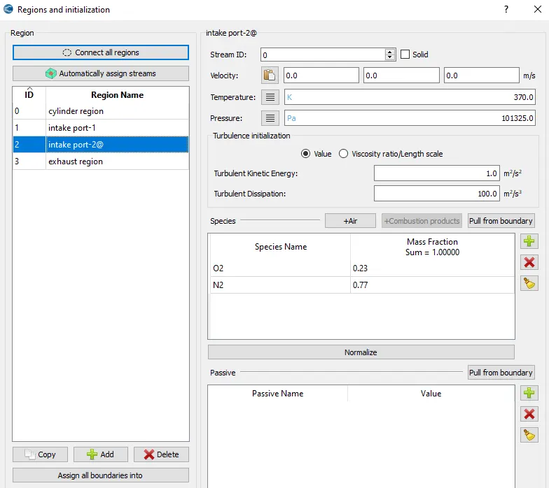
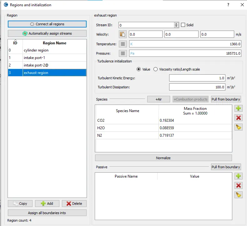
Regions and Initialisation
The fuel used is isooctane (IC8H18)
The equation for combustion of this fuel,
`C_8H_18 + 12.5(O_2+3.76N_2)= 8CO_2 + 9H_2O + (3.76*12.5)N_2`
From this equation the mass fraction of each species is found out.
`CO_2`= 0.192304
`H_2O` = 0.088559
`N_2` = 0.719137
Cylinder region
Intake port-1
Intake port-2
Exhaust region
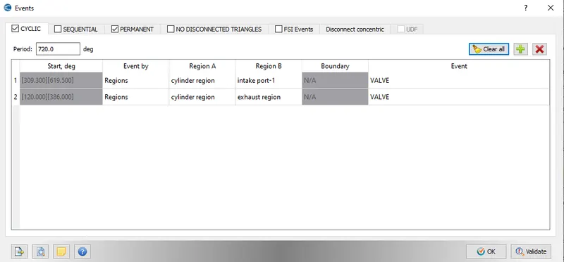
Events
Using cylic option in the events tab, intake port-1 and exhaust region are connected and disconnected with the cpmbustion chamber based on valve timing.
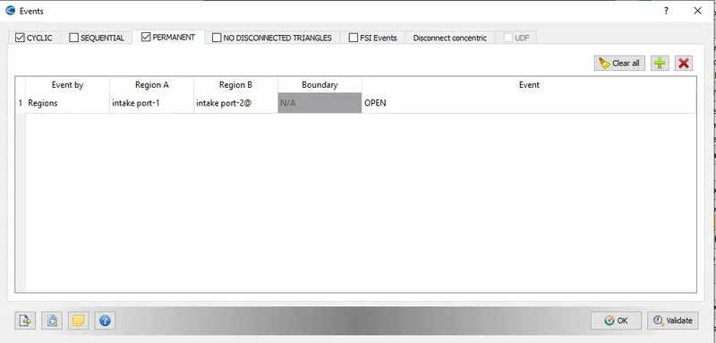
These two regions are always open to each other.
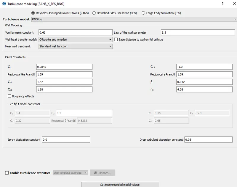
Turbulence model
Base grid size is given as 4mm.
RESULTS
Animation videos are provided in the below link:
https://drive.google.com/file/d/1FOSroXo2UUDn_qw8HKsbEufXDJfPQCdk/view?usp=sharing
https://drive.google.com/file/d/1yz7RVLWzZTgBVDo7LJ7xU0k8FOT-3Ok_/view?usp=sharing
CONCLUSION
The PFI surface preparation and boundary flagging was done in converge. The no-hydro simulation setup was done successfully and the animation video was uploaded.