Week 9: Project 1 - Surface preparation and Boundary Flagging (PFI)
Week 9: Project 1 - Surface preparation and Boundary Flagging (PFI)
AIM: -
In the Spark plug ignition gasoline engine, prepare the surface, boundary flagging and simulate the port fuel injection process with no hydro mode by using the Converge 3.0 Software.
INTRODUCTION: -
A single-cylinder gasoline engine completes a working cycle through four strokes of intake, compression, work, and exhaust. In this process, the piston reciprocates up and down. Each reciprocating motion is called a stroke, which completes the intake stroke, compression stroke, and work. With port fuel injection, gasoline is sprayed into the intake manifold, where it mixes with air, and then is sucked down into the cylinders. Direct injection places an injector on each cylinder, spraying gasoline into the cylinder itself. It will increase the efficiency of the engine and also decrease the emission characteristics of the engine. Using the converge 3.0 software creating the surface preparing and boundary flagging for the simulation process.
PROCEDURE: -
Step 1: Create the Piston and valve set up any one of the modeling and assembly software and convert it to the .stl file format. Using the converge software 3.0. first of all, upload the required .stl file of the PFI included the gasoline engine.
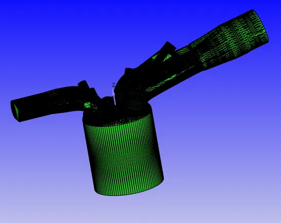
Figure 1: Single Cylinder four-stroke gasoline piston-cylinder set up modeling
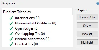
Step 2: After uploading the diagram using the diagnosis option, check all the geometric progress of the diagram can be done. The following options are should be converted as zero.
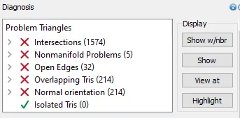
Figure 2. Problem triangles in the Four-stroke engine setup
Step 3: To reduce the errors, first have to set the boundary for each surface and hide the surface to analyze where the problem is created.
Step 4: To set up every boundary have to fix the separation in the geometry, using the boundary fence option easy to separate the boundaries.
Step 5: First of all, select the boundary option and flag select the inflow and outflow of the engine setup, it will be the main boundaries of the engine setup.
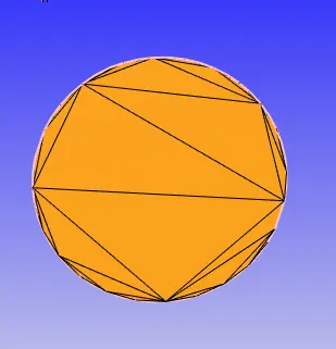
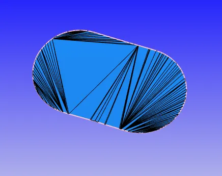
Figure 3: Inflow boundary of the Engine Figure 4: Outflow boundary of the Engine
Step 6: Using the angle option select the bottom of the engine cylinder surface and it's selected as the piston boundary.
Step 7: Using the boundary fence option, separate the top circle of the piston and bottom circle of the piston and select as the boundary and named as liner.
Step 8: After that, in this engine setup cylinder head to be the important boundary for neglecting the errors easily, using the boundary fence option, select the fence all the surfaces select the surfaces and name as cylinder head as shown below.
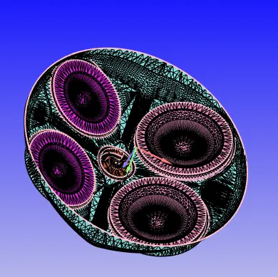
Figure 5: Cylinder head boundary surface of the gasoline engine set up
Step 9: Create the valves for the inlet and outlet region of the flows, in that valves are can be converted to three different boundaries for the inlet valve is separated as inlet valve top, inlet valve angle and inlet valve bottom.
Step 10: For the exhaust valve also separated as exhaust valve top, exhaust valve angle and exhaust valve bottom as mentioned below.
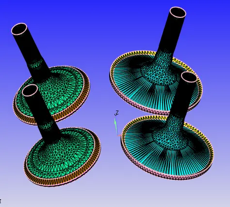
Figure 6: Inlet and Exhaust valves boundary flagging
Step 11: After that, the outlet port is to be separate from the exhaust valve, outlet and cylinder head, select the balance total exhaust area is selected one boundary and named as outlet port.
Step 12: For the inlet port also separate from the inlet valve, inflow and cylinder head, select the balance area select as the boundary and named as inlet port.
The inlet and outlet port boundaries are shown below,
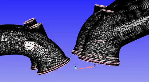
Figure 7: Inlet and outlet port boundaries flagging
Step 13: All the boundaries are flagging, some intersection errors are identified using the diagnosis option, to rectify the errors to move the inlet valve top, bottom and angle are should be moved from the inlet port.
Step 14: To move the inlet port select the option to transform à Translate à Selected boundaryà Select the Inlet valve top, angle and bottom boundaries à to identify the directional vectorà measure à location à average of vertex location à select the top of the inlet valve circle three-point location à set the translation amount as 0.003 m to remove all the intersections in the single cylinder four-stroke gasoline engine
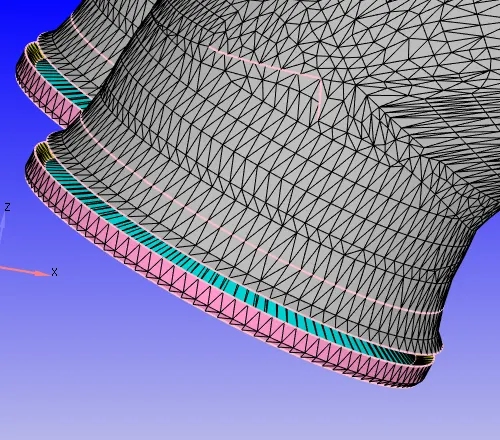
Figure 8: Movement created in the inlet valve boundary flagging
Step 15: In the boundary flagging, regarding the gasoline engine have the spark plug part in the cylinder region, in that the spark plug terminal and spark plug have different temperatures. So, the boundary separation needed for the cylinder head and spark plug terminal and also the spark plug as mention below.
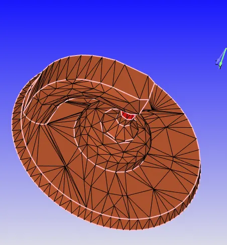
Figure 9: Spark plug and terminal flagging from the cylinder head
Step 16: Clear all the intersections, some open edges are can be present in the setup, using the repair option --> click patch --> free edge loop --> select open edges, all the open edges are cleared for the given diagram.
Step 17: After that all the errors are should be cleared in the given single-cylinder four-stroke gasoline engine using the diagnosis option clear as mention as below
Step 18: After that, all the surface setup and boundary flagging, set the regions for the engine setup. In this engine have 4 different types of regions are created.
1. Cylinder region
2. Intake Port - 1
3.Intake Port - 2
4. Exhaust region
Step 19: After the creation of the regions, to separate the boundaries into the required regions, convert all the boundaries into the four regions as mentioned below,
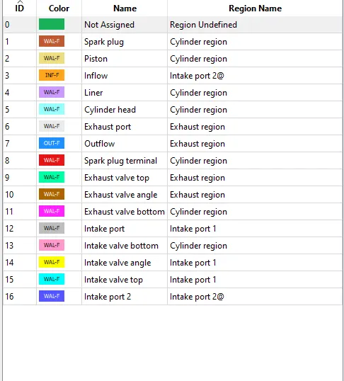
Figure 10: Boundaries and their respective regions selection
Step 20: In that gasoline engine set up has the different type of boundary conditions and each boundary conditions having the different temperatures, the boundary conditions and also temperature also mention below
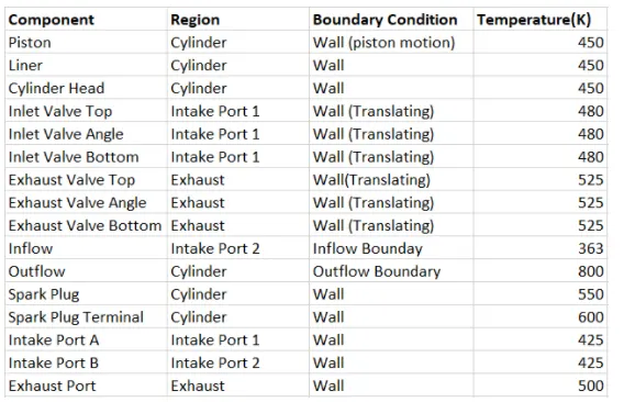
Figure 11: Diffrent type of boundary conditions and temperature of the boundaries
Step 21: For the inlet and outlet valve walls are having movement in nature, so that the input files are added for the valve movement in inlet and outlet.
Step 22: For the simulation parameters the start time of the simulation is set as -480 degree and end time of the simulation is set as 240 degree and click ok then done.
Step 23: Events are worked in the converge software is connecting the two boundaries with the opening and closing time setups, so event must be created for the valve opening and closing setup and also event created for the inlet port 1 and inlet port 2.
Step 24: For the valve movement is type of the cyclic movement, so it set in the cyclic condition, the event between the inlet port 1 & 2 is permanent process, so event created in the permanent process.
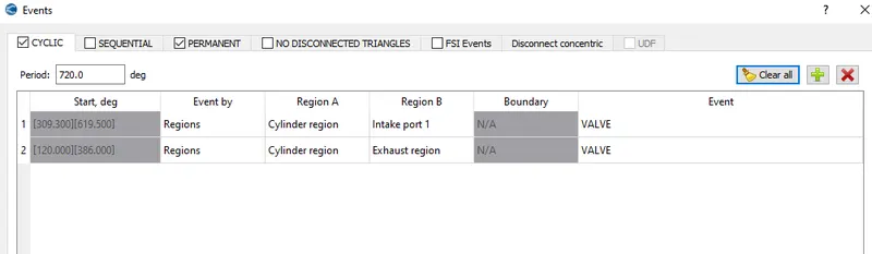
Figure 12 : Event creation between the two different boundaries
Step 25: For the gird selection initial setup as base grid selected as 0.004 m. Here fixed embedding is necessary for the intake and outlet valve edges are shown in below
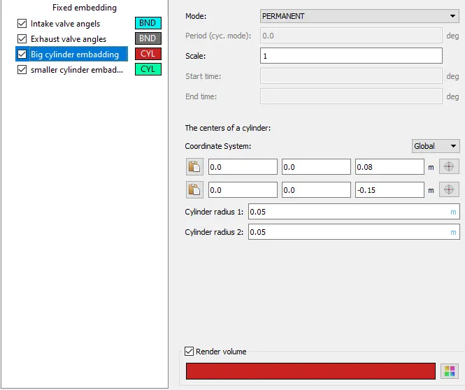
Figure 13 : Fixed Embadding for the inlet and outlet valve angle setup
Step 26 : The embedding also necessary for the cylinder region, so that two different region embedding is created as shown in figure below, 1. Large cylinder region 2. Small cylinder region
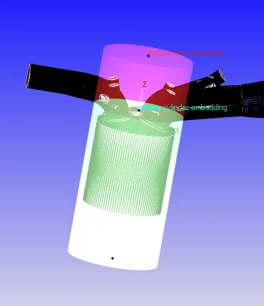
Figure 14: Embadding for two different region
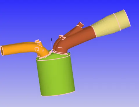
Figure 15: Seperated the regions in colour
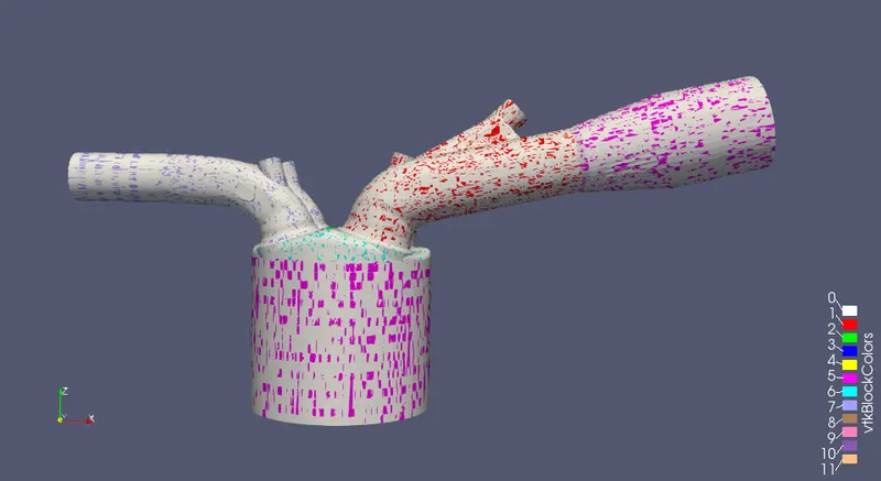
Figure 16 : After the post processing set up in para view software
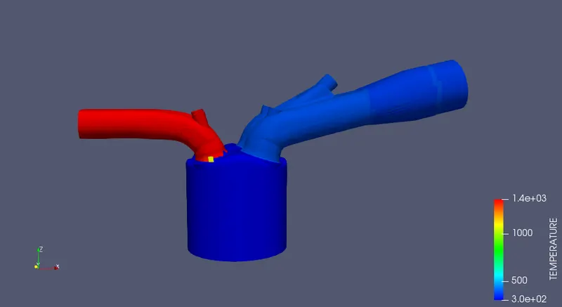
Figure 17: Initial temperature distribution of the Cylinder-piston set up
Conclusion: The single cylinder four stroke gasoline engine with port fuel injection system set up surface preparation and boundary flagging is completed by using converge 3.0 and no hydro simulation completed by using para view software successfully.
Youtube Link : https://youtu.be/5fjpYQL1y8s