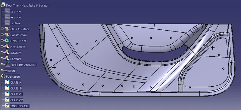
Week 9 - Project_1 - Door Trim Lower with Engineering Features
AIM
To create the Door Trim Lower Plastic component through the given Class-A surface. Also create the Heat Stakes and the locators considering the design rules.
REPORT
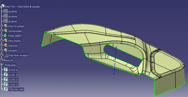
1. Creation of tooling axis
- Identify the best possible direction for creating the tooling axis.
- First extract the partiicular surface.
- Create a point on the centre of that surface.
- Draw a line normal to the surface passing through the point.
- That is our tooling axis.
2. Draft analysis on class A
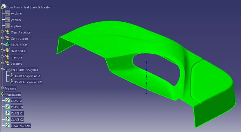
- Once the tooling axis is obtained, we conduct draft analysis on the class A surface with the help of tooling axis. This helps in determining weather the tooling axis we created is right or wrong.
- Click on the draft analysis option.
- Click on the compass icon and place the compass on the tooling axis.
- Click anywhwere on the surface to generate the analysis result.
- From the result it is clear that the surface has passed the draft analysis test.
3. Creation of B surface
- First offset the class A inwards by 2.5 mm.
- The offset surface can be seen with many patches.
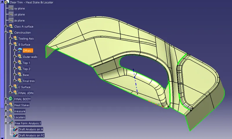
- Extract each surfaces one by one using multiple extract option and then using boundary, extrapolate them.
- Use other options like multi section surfaces to fix certain patches.
- Use join to join the mss with the surface.
- Use the trim option to trim all these surfaces together.
- Apply edge fillets on all the sharp corners accordingly.
- B surface is thus created.
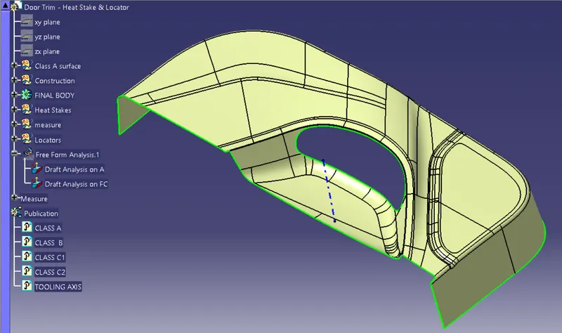
4. Creation of C surface
- Select the boundary option and select the outer boundary of Class A.
- Using sweep command sweep the surface for 90 degrees inwards in the base region.
- Then select the front regions seperately with multiple boundaries and sweeps for 93degrees.
- Extrapolate and trim them together
- Then select the inner boundary and repeat the same steps.
- We get both the C surfaces.
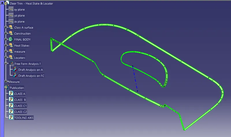
5. Final join
- First join Class A with both the C surfaces.
- Then using trim option, trim the A+C surface with B
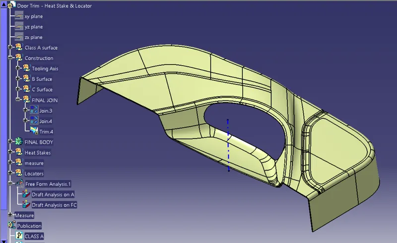
6. Creation of final component/closed surface
- Once the final join is complete, we open part design and select closed surface option.
- Click on the surface to create a closed surface.
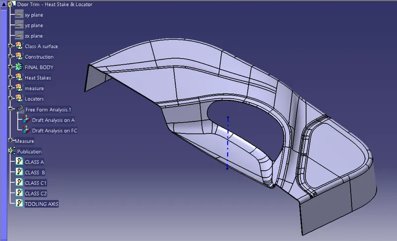
7. Locators
Locators help in clamping down the part. Placed against the locator, the workpiece cannot move. There are two types of locators called the 2 way locator and 4 way locator which stops resists its 12 degrees of freedom of motion.
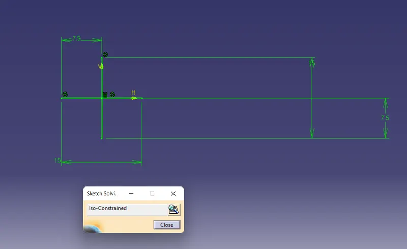
- To design a 4 way locator we draw a sketch as shown below.
- We then define the work on a part body and pad the sketch selecting the thick option
- Then we give draft of 0.5 degree to it.
- Then we chamfer the corners 3*45 mm
- Then we fillet the edges for 0.25 mm
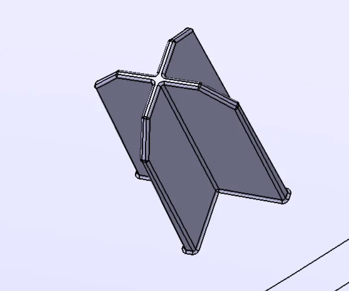
- Then we click on insert the pad in new option.
- Copy and paste the body in the main heading.
- Use transalate option to move the new 4 way locator to other end of the body.
To design a 2 way locator, we draw the below sketch.
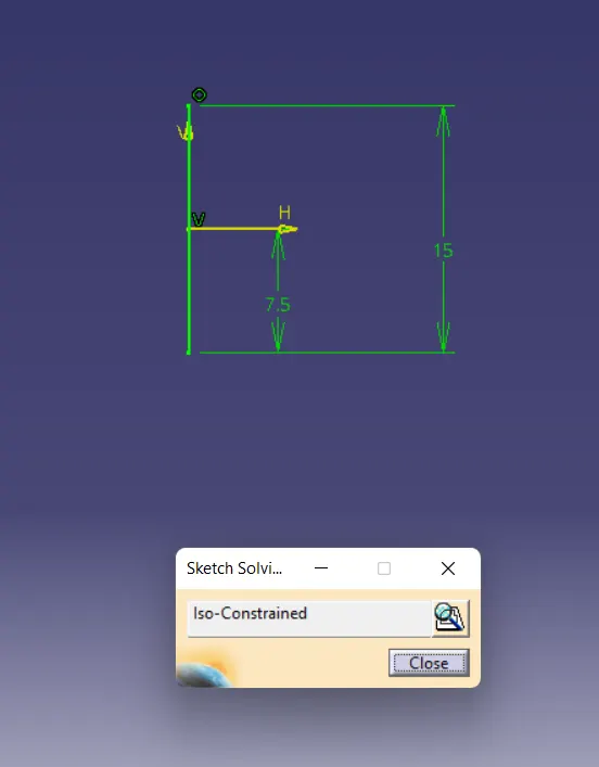
- We follow the same steps as we did for creating a 4 way locator.
- We pad it, draft it, apply chamfer and fillets.
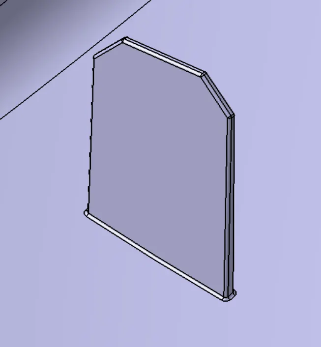
Once that is done we add all these components to the main body using union trim option.
8. Heat Stakes
Thermal staking or heat staking is an assembly method that uses the controlled melting and reforrming of a plastic stud or boss to capture or lock another plastic or metal component of an assembly in place. The plastic stud protrudes through a hole in the component to be locked in place. The thermal heated tip contacts the top of the stud, which melts andfills the volume of the tip cavity to produce a head locking the component in place.
- We first draw the following sketch.
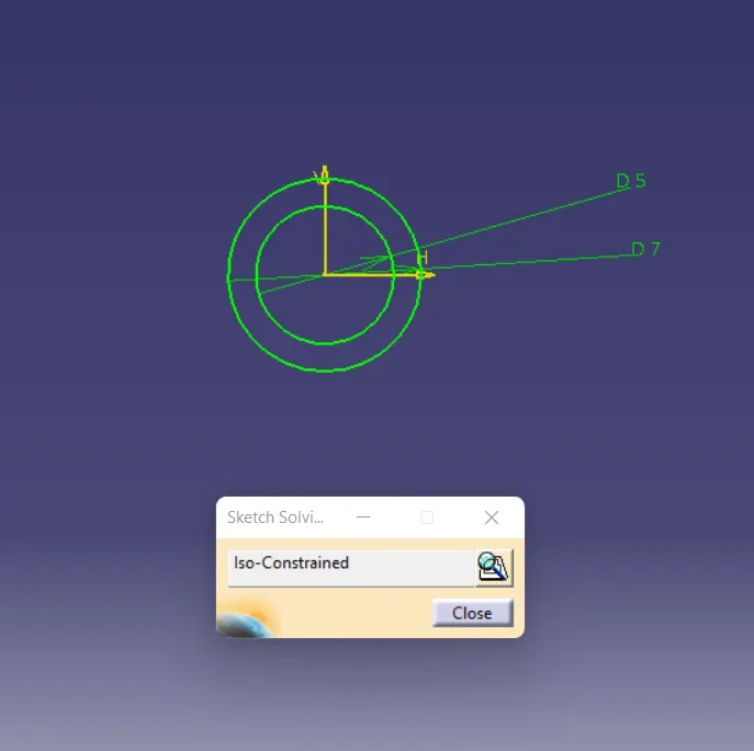
- We then pad it to around 4mm less than the locators.
- We draft them 0.5 degrees
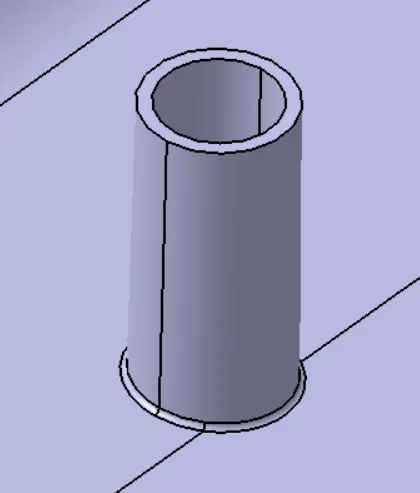
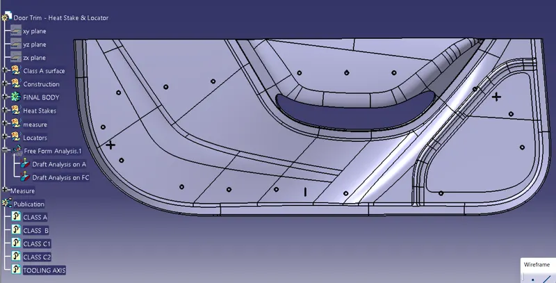
- After this we transalate the heat stake to around 15 different points alongside the boundary of the component.
- After that all heat stakes are assembled in a single body
- The that body is added to the main part using union trim.
- Fillet the joining region.
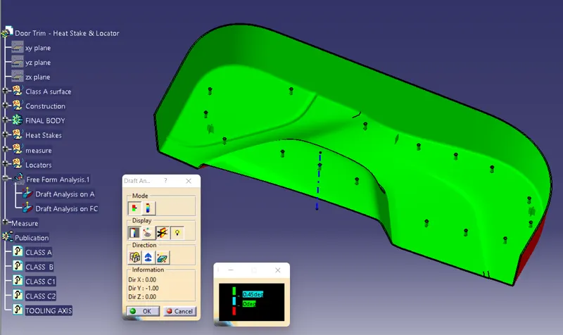
9. Draft analysis on the final component
- Follow the same procedure for draft analysis done on A for the finished component.
- From the results it is clear that the components passes the analysis.
RESULTS
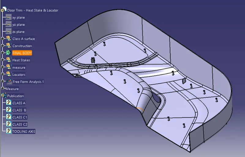
1. ISOMETRIC VIEW
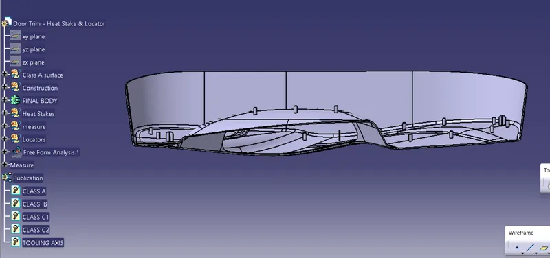
2. FRONT VIEW
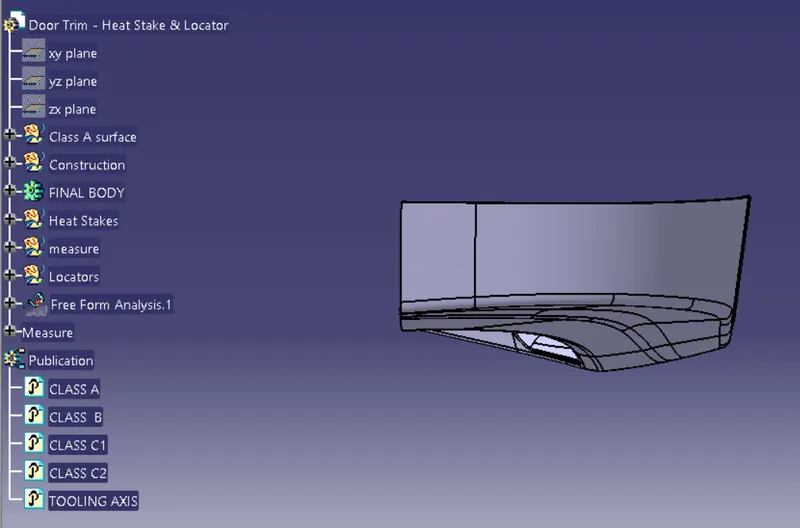
3. SIDE VIEW
4. TOP VIEW