Week 9 - Project 1 - Door Trim Lower with Engineering Features
AIM:
Create the Door Trim Plastic component through the given Class-A surface. Class-A Surface should be created meeting the requirements of the draft angle and at the end perform the Draft analysis on the model. Then Create the Heat Stakes and the locators considering the design rules
OBJECTIVE:
- To crate a tooling axis for the plastic component
- To create a Door Trim of plastic component from given Class A surface.
- To perform the draft analysis over the plastic component.
- Create the Heat Stakes and the locators considering the design rules
IMPORTING THE MODEL
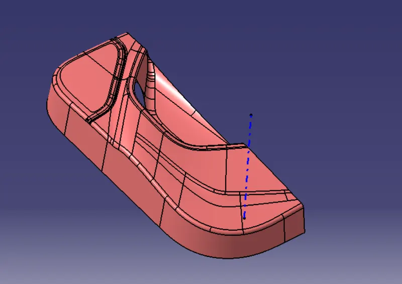
- Open the downloaded IGES file make it has class A surface by jioning all the surfaces
PROCEDURE:
- Doing the continuity check to ensure whether given class A surface is continuos or not.By using Boundry/jion method,It seems there is no dis-continuos boundry
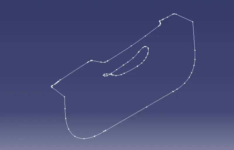
- create point on Class A surface plane & create tooling axis on point & normal to surface (On surface method)
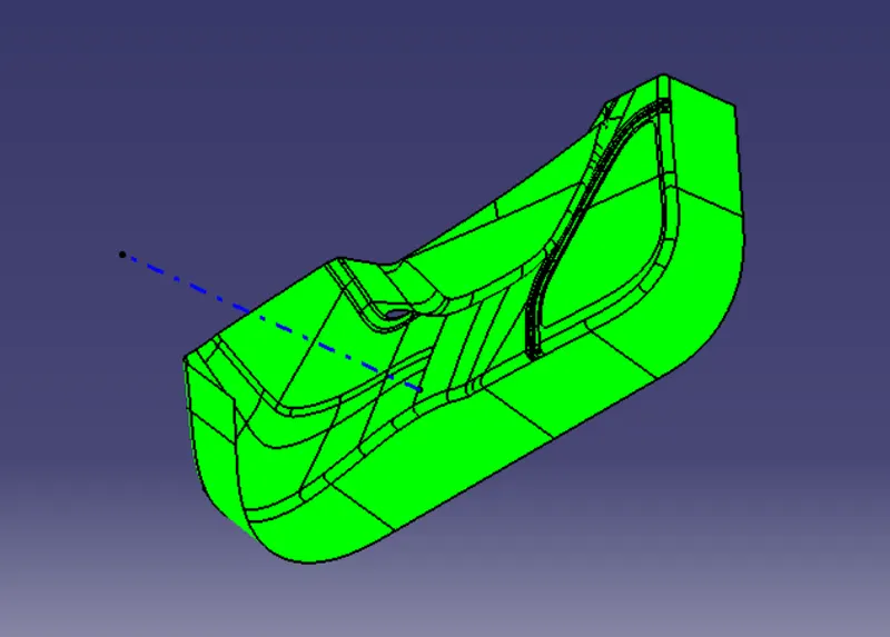
- Perform draft analysis on the given class A surface,Below pic shows the result of draft analysis,It cleares that it has 3^0 draft throughout the surface with respect to tooling axis as it is in green color
Creating Class B surface:
- In this component Directly offset class A surface to 2.5 mm
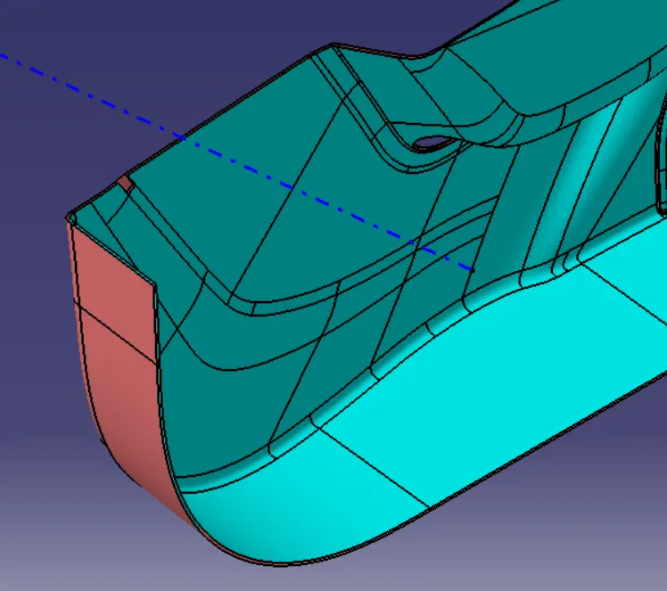
- Then repair the patches of class B surface
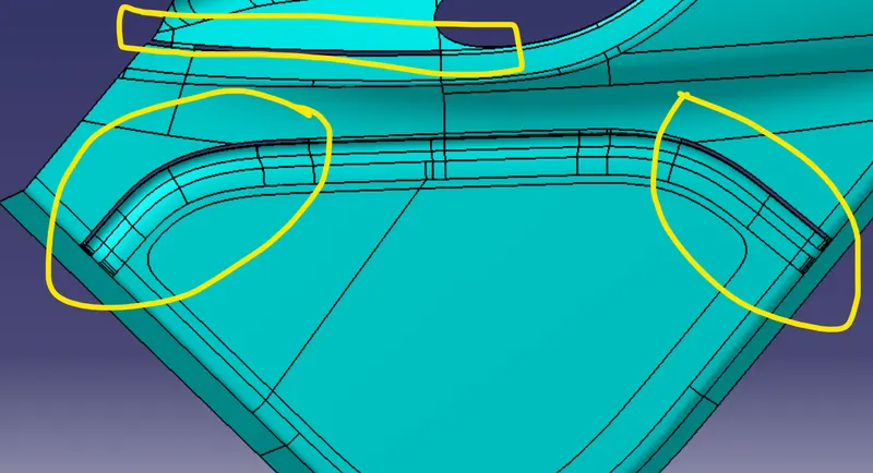
- To repair used the operations like multi surface,trim, jion etc with help of tools like line,spline obtain the class B surface
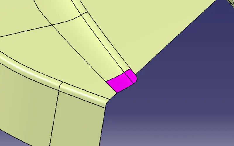
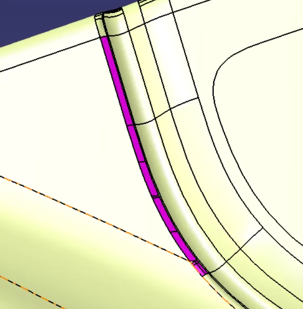
- Similarly did the above procedure for All the Patches
- The finle Class B
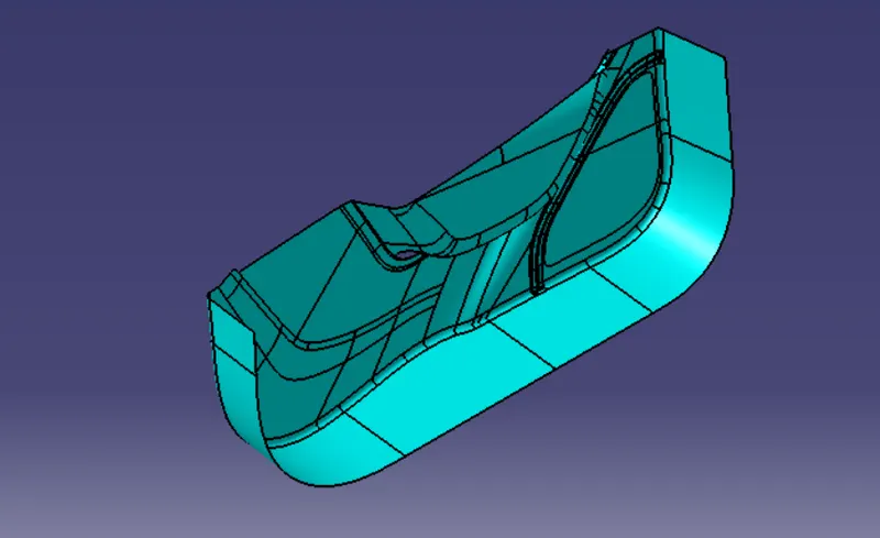
Creation of Class C:
- Extract all the boundry of class A surface Separately by observing the complexity ,Then sweep them
- Trim them together then we will get Class C surface
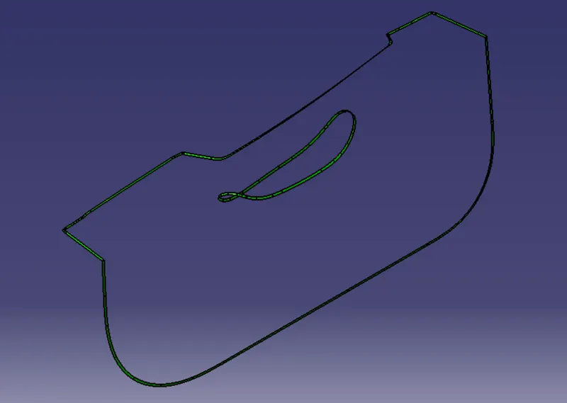
- Jion the class A & class C surface(by trimming)
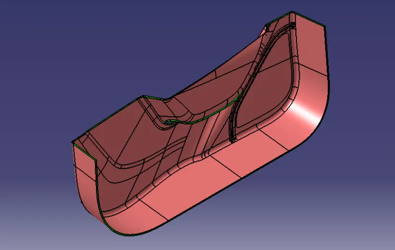
- Then jion all the Class A,B & C Surfaces
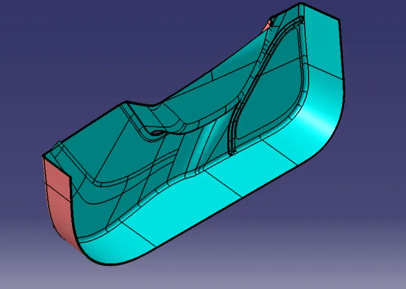
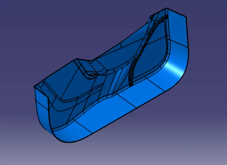
- Then convert this closed surface to part body in the part workbench,we will get the required Door Trim
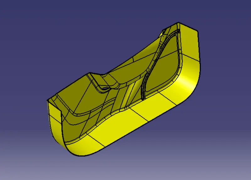
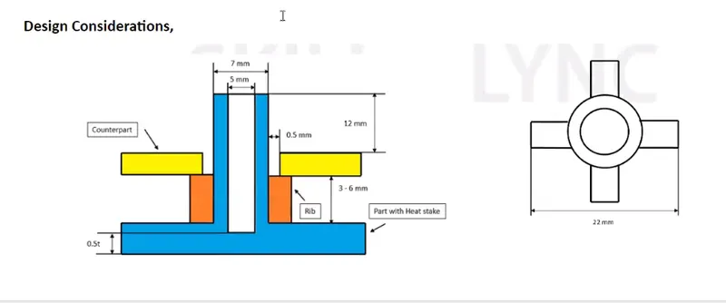
- Then Create the Heat Stakes and the locators considering the following design rules
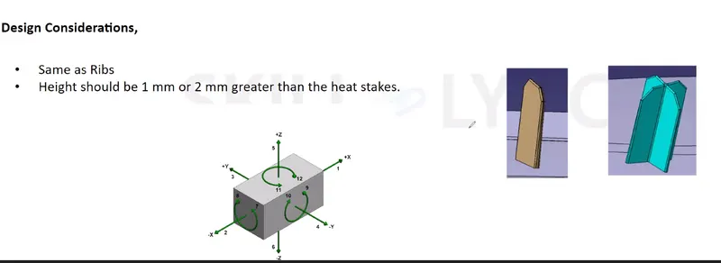
- perform the Draft analysis on the Finle model.
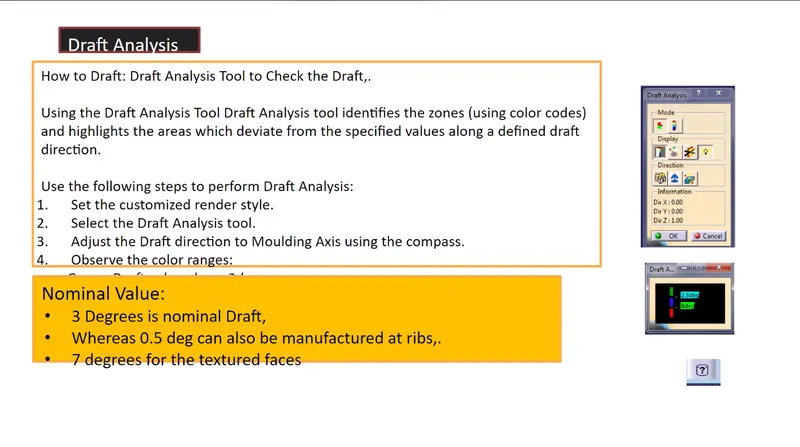
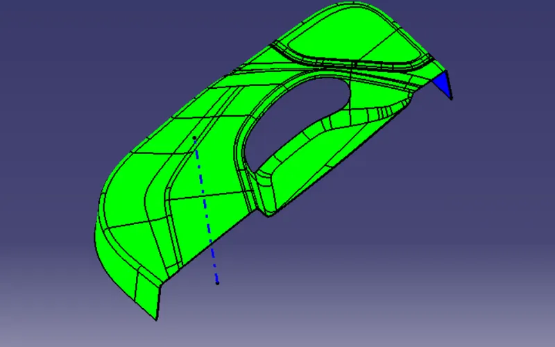
From the above figure we can observe it is satisfying 3^0 nominal draft
- perform the Draft analysis on the Finle model. ( with Respect to heat stakes & locators)
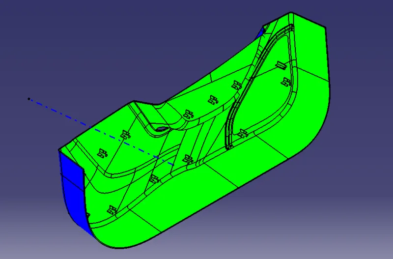
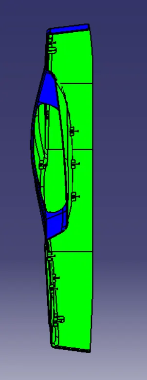
From the above figure we can observe it is satisfying 0.5^0 draft on all the Heat Stakes and the locators
- solid model with the proper color code of the draft angle in various orientations
- green- 0.5^0
- Red- 0^0
- Blue- negative side
- Isometric view
- Front view
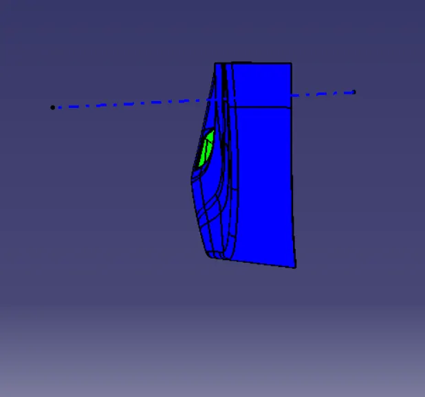
- Side view
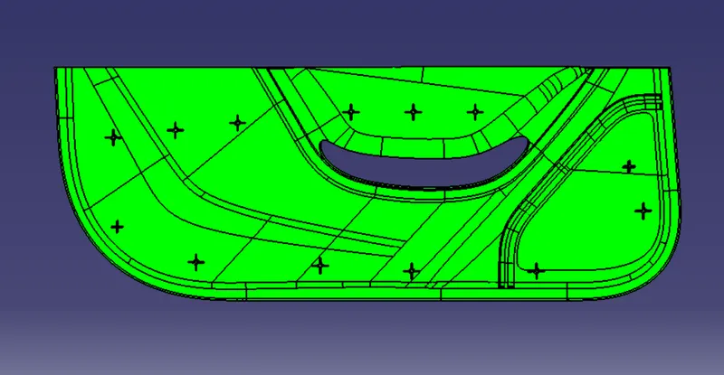
- Top view
CONCLUSION:
The Plastic Component is created & Draft analysis is Done