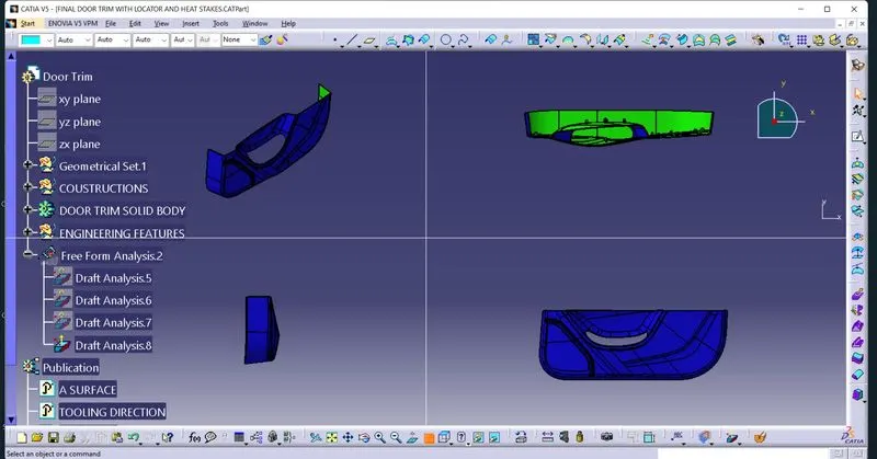
Week 9 - Project 1 - Door Trim Lower with Engineering Features
Week 9 - Project 1 - Door Trim Lower with Engineering Features
AIM:- Create the Door Trim Lower Plastic component through the given Class-A surface. To begin with, the tooling axis for the given Class-A Surface should be created meeting the requirements of the draft angle and at the end perform the Draft analysis on the model.
Create the Heat Stakes and the locators considering the design rules mentioned in the video for the door applique.
FIRST CHECK THE A-SURFACE WHICH PROVIDED:-
Before starting the creation of the class B surface we must ensure that the given class A surface is properly closed and the surface continuity is proper. This can be done either with the help of the join operation or by using the boundary feature.
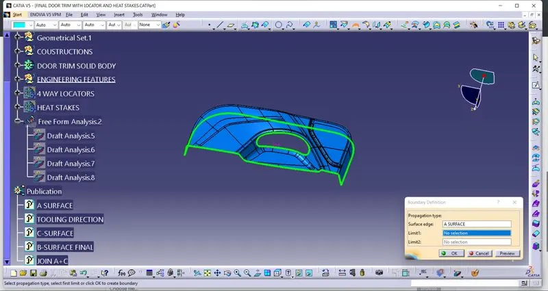
TOOLING AXIS:-
The Tooling Direction is basically the direction that the mold pulls a part. The mold is built in two separate pieces, basically. You have a Cavity side and you have the Core side. The Core pulls apart from the Cavity and that's the Dye line or the Tooling Direction.
- After analysing visually for the best possible tooling axis, an axis system is created on the centre of one of the surfaces of the door trim.
- The main tooling axis is created normal to the y direction
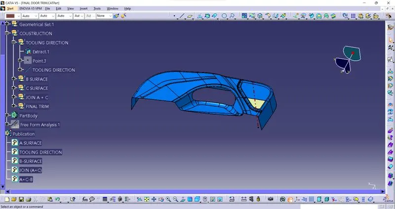
DRAFT ANALYSIS:-
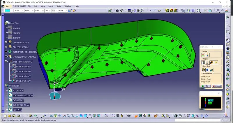
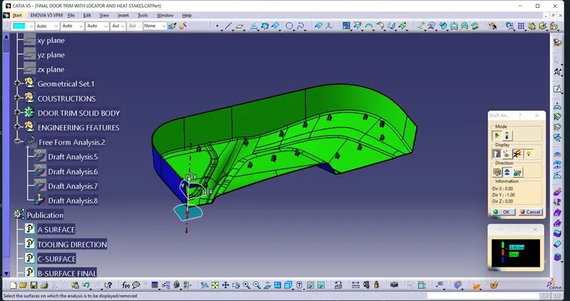
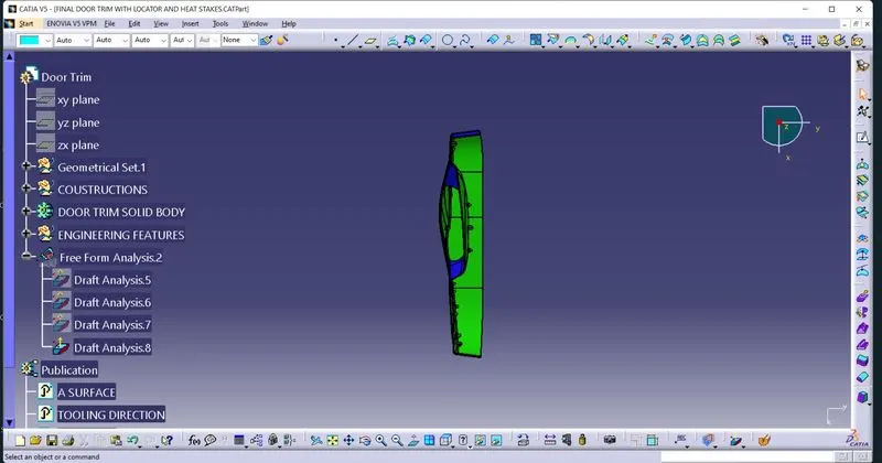
The Draft Analysis command enables you to detect if the part you drafted will be easily removed.
- In the colour scale change the draft angle to 3 degree.
- The component changes to green in indication of passing draft angle.
- Use running point to check the angle on the component.
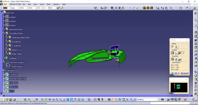
B-SURFACE:-
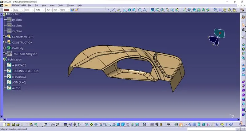
- Extract the surfaces from the class A using multiple extract and untrim them.
- Use Extrapolate to make sure that all the untrims are properly intersected to trim and offset the surfaces to 2.5 mm to create the thickness.
- Insert them into new geometrical set and name it with respective part names.
- After offsetting many openings in the surfaces are found which are closed with the help of sweep, multi sections-surface command.
C-SURFACE:-
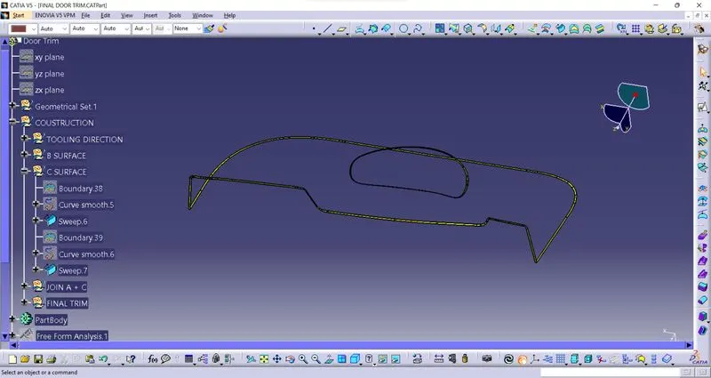
- Extract the boundary from the class A surface using boundary command.
- Using disassemble tool to divide the boundary as the boundary contains domains.
- Use sweep command > choose profile type line > subtype as with draft direction > choose guide curve and draft direction > draft angle as 3 degree > preview.
JOIN A+C SURFACE:-
TRIM B FROM A+C SURFACE:-
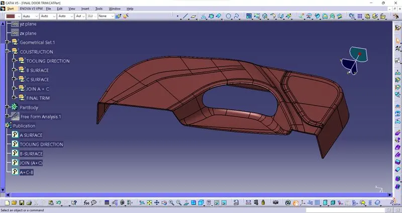
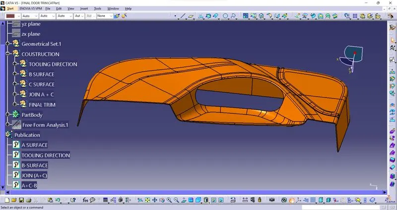
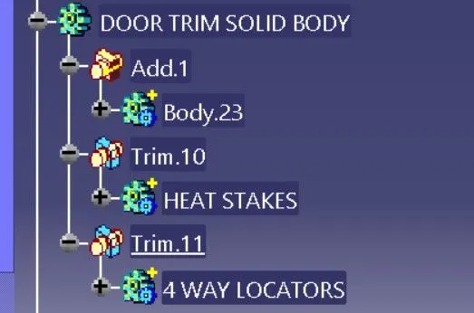
The final trim is created by joining the Class A and C surface and finally trimming it with the Class B surface. The combination of class A, B and C surface is then converted into a solid with closed surface command in the part workbench.
SOLID BODY:-
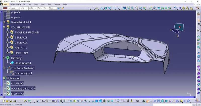
DRAFT ANALYSIS:-
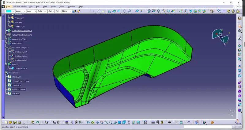
ERROR:-
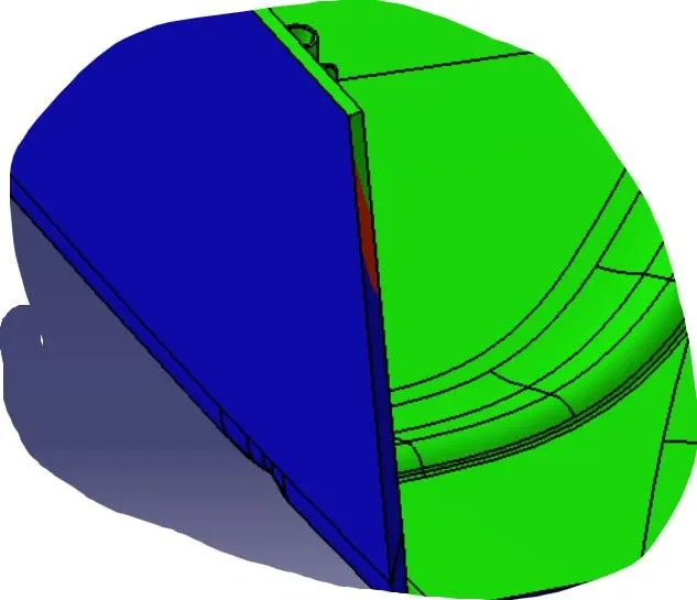
DUE TO THE A-SURFACE
ENGINEERING FEATURES:-
LOCATOR(4 WAY):-
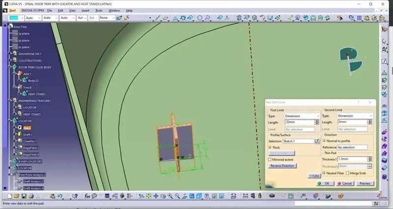
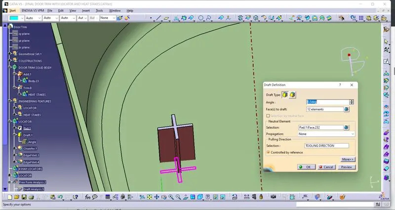
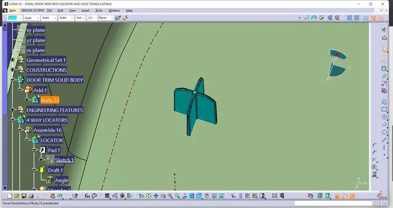
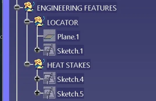
To create the locators, I created a sketch 15/15 on the body. After creating the sketch, I pad it 20mm in height and thicken it to 1.3mm and I drafted it with 0.5deg in the direction of the tooling axis. I gave 3mm of chamfer with 45deg of inclination and after I gave a fillet of 0.3mm radius.
4-way locator:
SKETCH:-
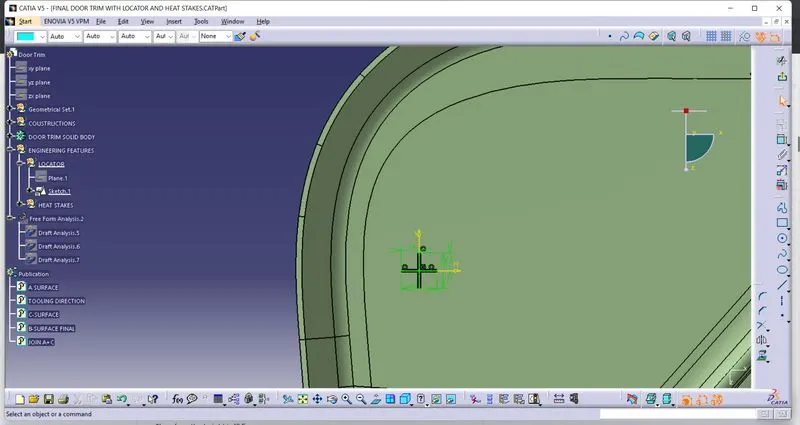
PAD:-
DRAFT:-
FINAL LOCATOR:-
HEAT STAKES:-
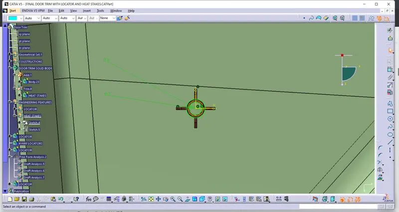
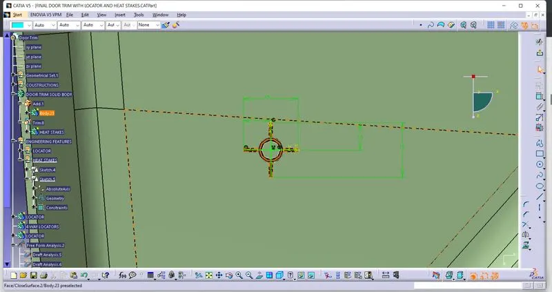
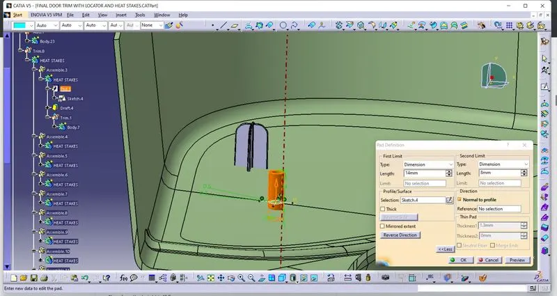
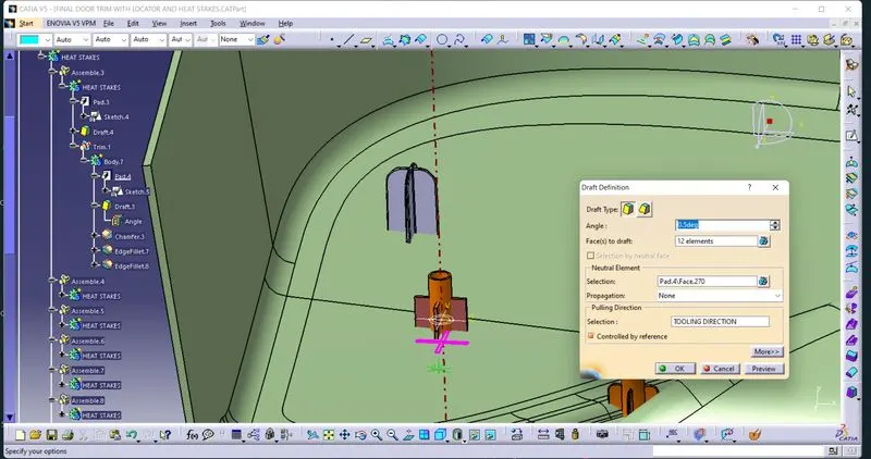
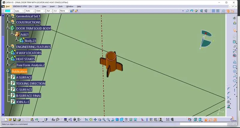
To create the heat stakes, I draw a sketch on the surface. After the creation of the sketch, I pad it to 14mm height and I gave a draft angle of 0.5deg on both sides (inside and outside) and then I gave a fillet with a 0.25mm radius. After creating the heat stake, I created the ribs for supporting purposes. To create the ribs, I draw a sketch and padded it to 7mm in height and 1mm in thickness. After padding the ribs, I drafted 0.5deg in the tooling asix direction and filleted it with a 0.25mm radius. Finally, I union trim the ribs with a heat stake to remove the ribs, which are present inside the heat stakes.
Heat stake sketch:
SKETCH:-
PAD:-
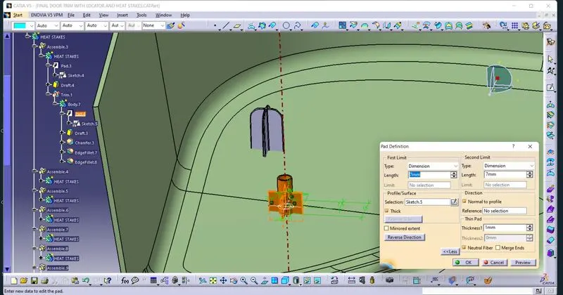
DRAFT:-
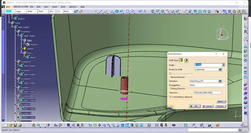
FINAL HEAT STAKES:-
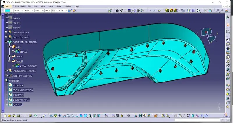
Now I translated the heat stakes by copy-pasting them in the part body according to the requirement.
Final part body with 4-way and 2-way locators including all the heat stakes with supporting ribs:
DRAFT ANALYSIS:-
2.9 degree:-
0.45 degree:-
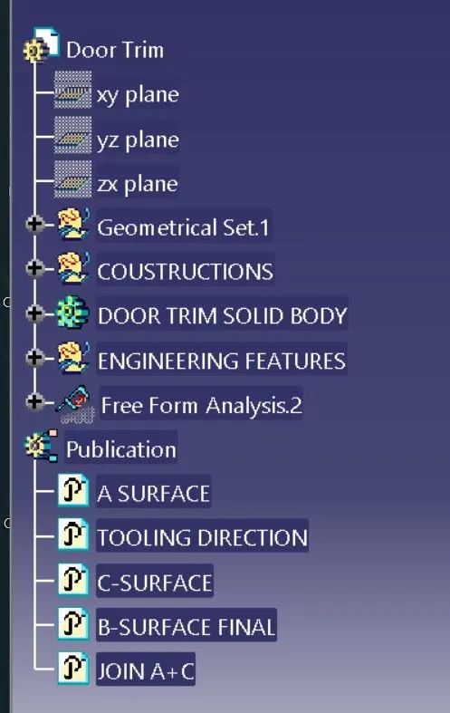
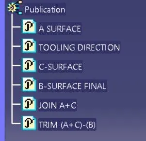
GEOMETRICAL TREE STRUCTURE:-
VIEWS:-
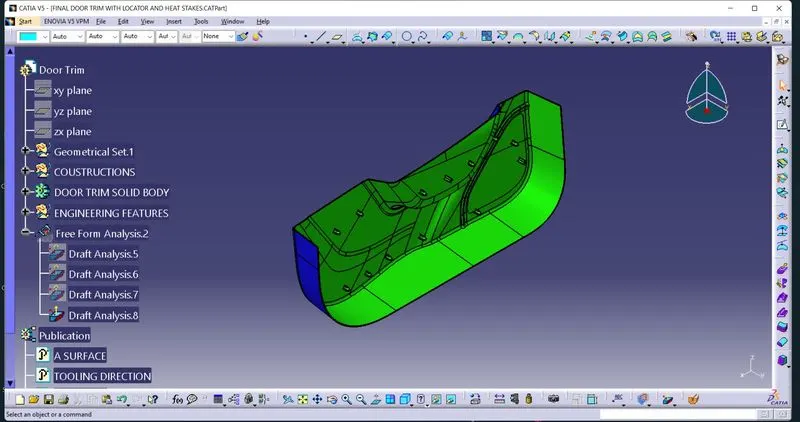
ISOMETRIC VIEW:-
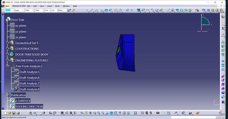
FRONT VIEW:-
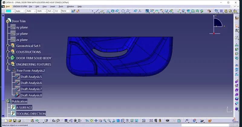
SIDE VIEW:-
TOP VIEW:-
ALL VIEW IN ONE FRAME:-