Week 9 - Project 1 - Door Trim Lower with Engineering Features
The given class-A surface.
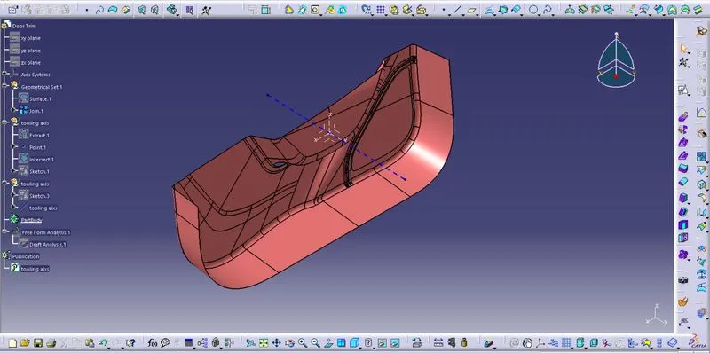
creation of tooling axis:
The tooling axis is created using the outer walls of the class-A surface. First, extract a patch of surface and place a point on it. Insert an axis system and intersect it with the class-A surface. Now we have an intersection curve. Using this we draw two lines on either side of the reference point and coincide them with the intersection curve. Now using bisecting option select the two lines and the point as a reference we get a line. This is our tooling axis with respect to our side walls.
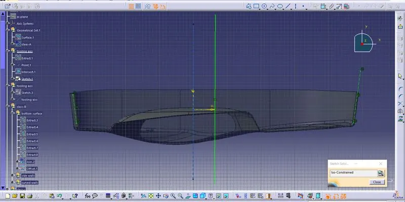
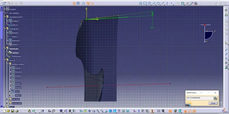
With respect to the Base surface, we create another line using the edge of the base surface. The angle between the line drawn and the extracted edge is 3.5deg.
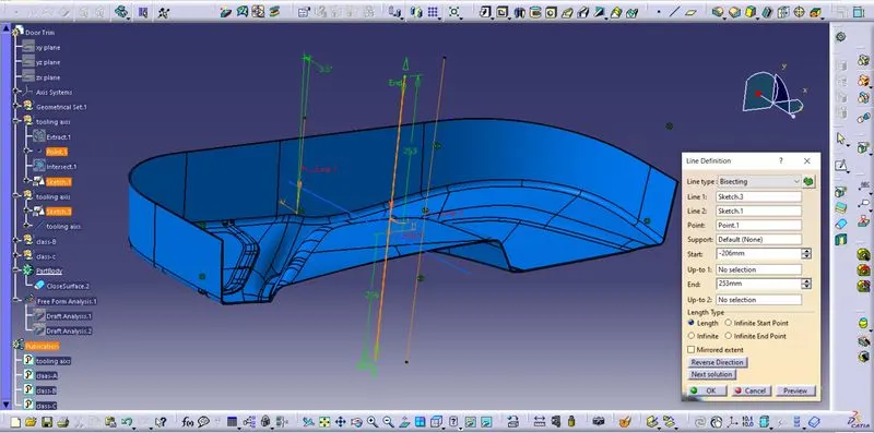
After creating these two lines, we use bisecting method and select these two lines to get the required tooling axis.
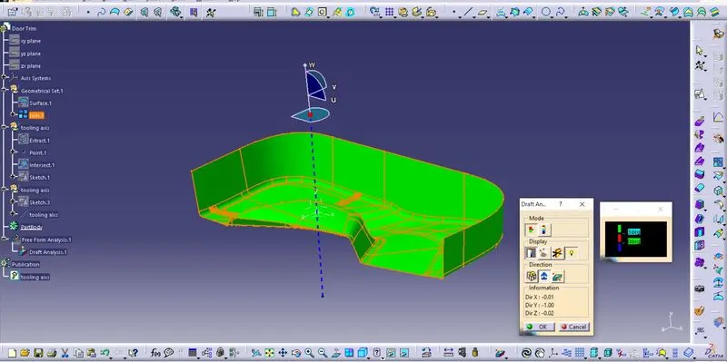
Once the tooling axis is created we do the draft analysis on the given class-A surface to check whether it is feasible to make a class-B surface out of it. The daft analysis of the class-A surface is shown below.
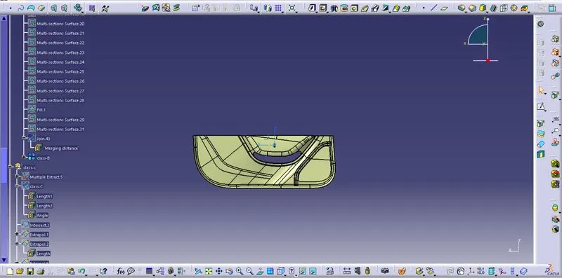
once the draft analysis is satisfied, we proceed to create the class-B surface. We mainly use extract, join, offset, and multisection surface to create the class-B surface. Extract the base walls, join them, and offset them. If there are any gaps between two offset surfaces use the multisection surface option to fill the gaps. The created class-B surface is shown below.
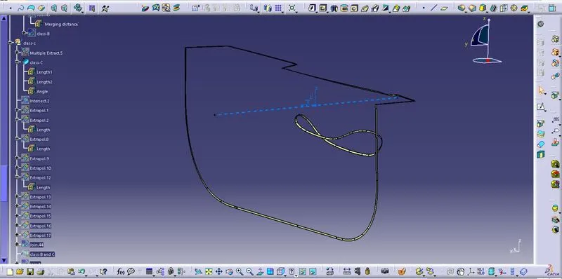
After creating the class-B surface we need to fill the gap between class-A and class-B surfaces. To do that we need to create the class-C surface. Extract the boundary of the class-A surface. Using the sweep option, the extracted boundary is the guide curve and the reference surface is the class-A surface. The class-c surface is shown in the below image.
After creating the class-C surface we trim the class-B and class-C surfaces and create both as a single surface. The joined surface is shown below.
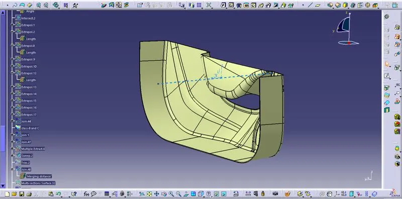
Once we joined both class-B and class-C surfaces, we unhide the class-A surface and join the class-A surface with the joined class-b and class-C surfaces. This is the final component with a thickness of 2.5mm.
Design of heat stakes and locators:
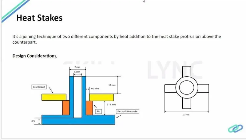
As we can see in the above image, the diameter of the hole is 5mm and the outer diameter is 7mm. And the height of the rib from the base should not be greater than 6mm. The images of the hole and the rib are shown below.
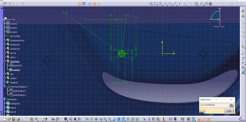
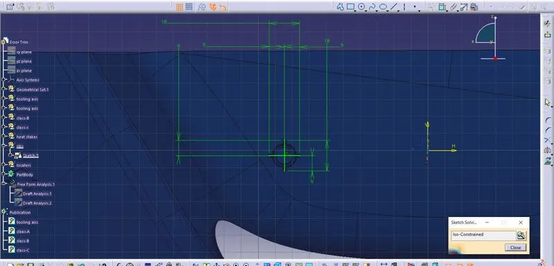
The width of the rib from one end to another is not more than 22mm as per the design criteria.
After sketching the hole and rib, we go to the part body and pad them to a certain height. Both the rib and holes are to be padded separately and then use union trim to join both the hole and rib. Before joining we need to provide the draft of 0.5deg to the walls of the hole and the ribs. Then we insert the edge fillet to the heat stake with 0.25mm.
In the given design there are points that are inserted and we have to place these heat stakes at those points. To do so, we need not draw the hole and ribs at every point instead we can copy the sketch and paste it into the main body and choose the translate option in the part workbench. From one point to another point we can translate the created heat stake. For all the 15 points that are given we have to copy and paste them into the main body and then translate to each and every point.
After we create all the heat stakes, now we need to place the locators at two points that are shown in the below image.
There are two types of locators one is a 2-way locator and the other is a 4-way locator. The 2-way locator arrests 2 degrees of freedom along one axis and the 4-way locator arrests 4 degrees of freedom in two axes. In the given image it is a 4-way locater. To create a 4-way locator we need to draw a sketch. The sketch is shown below.
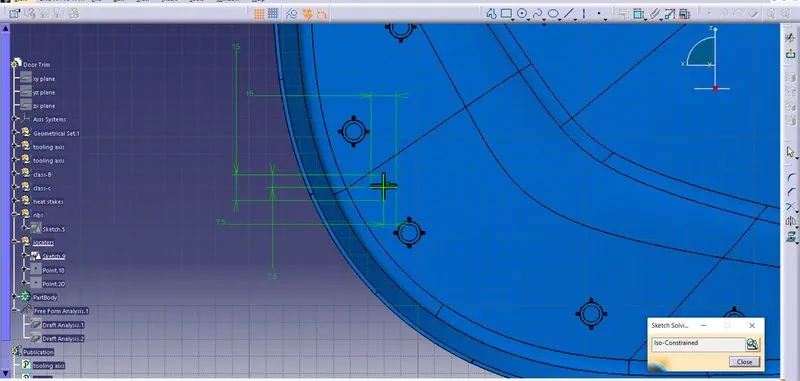
We created a sketch that looks like a plus sign and pad it using the pad option. while padding, select the thick option and give the neutral fibre reference as the tooling axis. Because the locator and the heat stakes should be extruded in the tooling direction itself. Once we got a locator we will translate it to the other location just like we did with the heat stake. The locator should be more in length than the heat stakes because the locators help in aligning and fixing two components and these are the ones which first come in contact with the mating part. The locators should be of the same length even though the surface has different curvatures at different points. Using the union trim option we attach the locators to the part body and after adding we provide a fillet of 0.25mm.
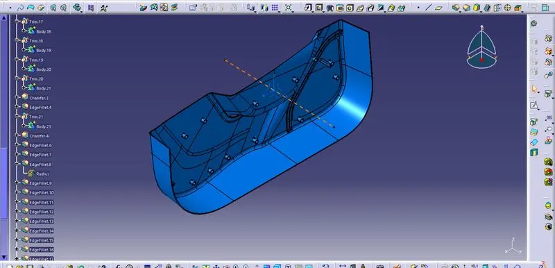
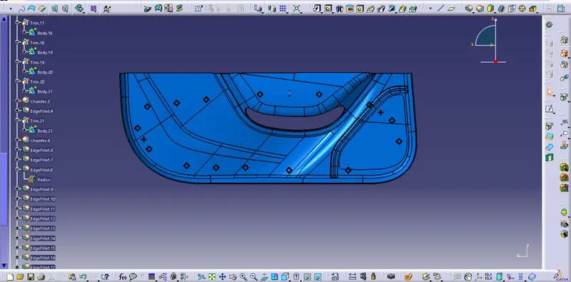
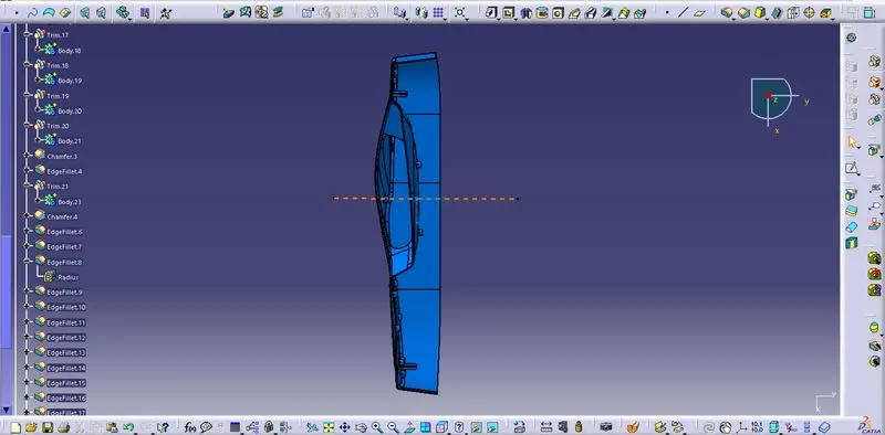
- Screenshots of the solid model with the proper colour code of the draft angle in various orientations (Isometric, Front, Side, and Top View).
Draft analysis of final component:
The green colour region indicates that the component satisfies the given draft angle of 0.5deg. But there is a certain red colour region which indicates that the draft angle is lying between 0 to 0.5deg. The 0.5 deg draft angle is the design criteria for heat stakes and locators. It should not be less than 0.5deg. So as per the design criteria the of heat stakes and locators the draft analysis gives this result.
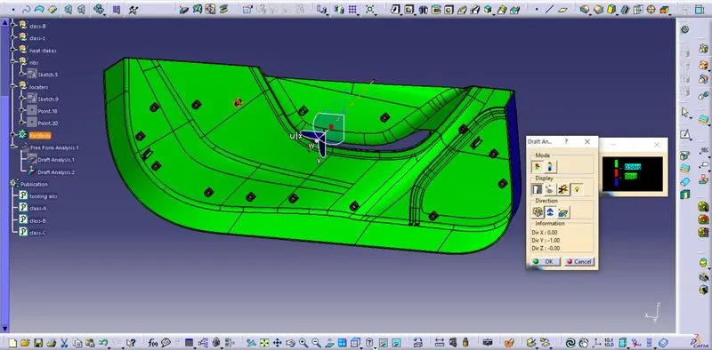
Conclusion: As per the given class-A surface we have created the solid body and added heat stakes and locators and performed draft analysis on both the class-A surface and the final component.