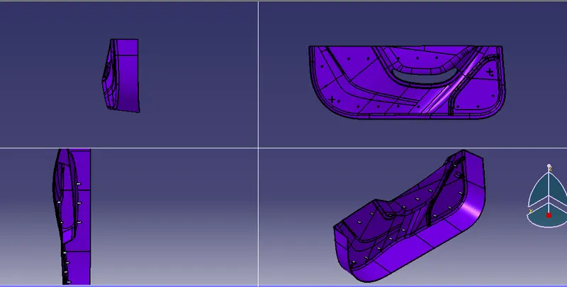
Week 9 - Project 1 - Door Trim Lower with Engineering Features
Aim :
To Create the Base Bracket Plastic component through the given Class-A surface. To begin with, the tooling axis for the given Class-A Surface should be created meeting the requirements of the draft angle and at the end perform the Draft analysis on the model.
OBJECTIVE:
- To create a Tooling axis for a class 'A' Surface, which meeting the requirement of the draft angle and to analyse the solid model.
- To create a the surface B and C Surface
- To create a report which explains the Draft analysis and Tooling Axis cration and colour scale varients.
- To attach the screenshots of the 3D Part Model in different orientations.
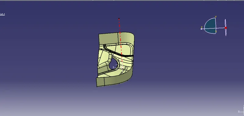
Tooling Axis:
The Dummy tooling axis is created to creat the main tooling axis.Take the intersection of the bracket body and make the lines in the deficult area in the bracket.Then Bisect the lines to create the tooling axis.
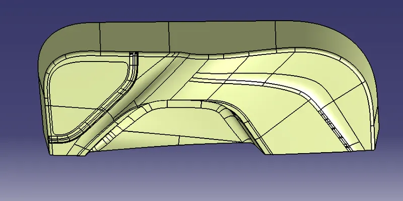
Class-B surface:
Class -B surface is created by extracting each wall and untrimming and extrapolating the walls to obtain the shape by trimming the excess surfaces and offsetting it to a certain distance based on the thickness of the model.The offset surface will be the B-surface.
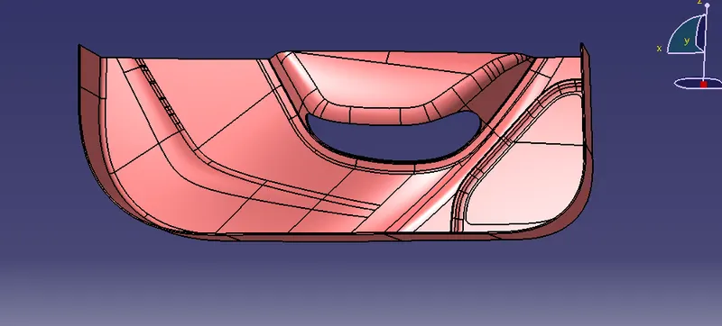
Class-C surface:
The surface created using sweep command by sweeping the boundaries of A-surface along the tooling axis to connect from A to B-surface is known as C-surface.
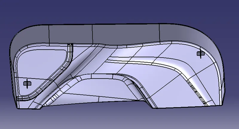
LOCATORS:
- These aremainly used to Arrest the Degrees of Freedom of the Plastic Component.
- Usually There are 2 way and 4 way Locators.
- Same rules as the Ribs are Followed.
- It also supports the Position of Plastic Component While Assembly or Joining of Components.
HEAT STAKES:
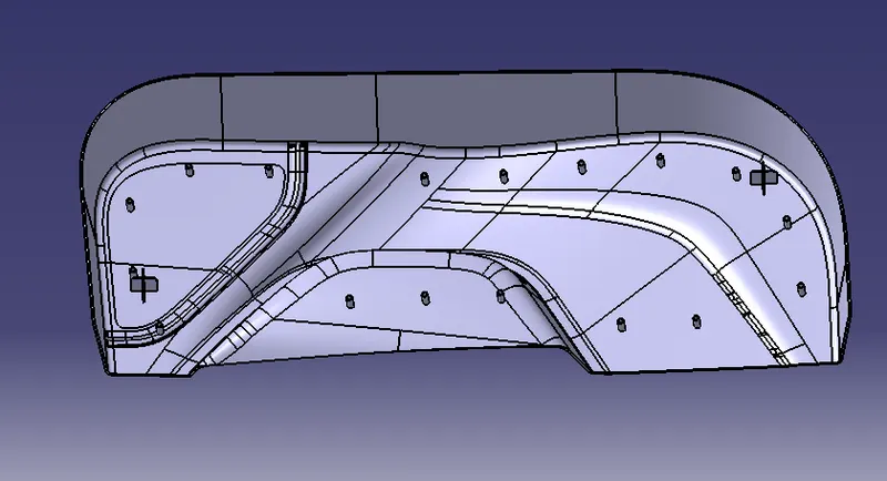
- Heat staking also known as Thermoplastic staking is the process of joining two Plastic Components together.
- Heat Staking is a pulsed-heat process to join two or more parts out of which one at least is made of plastic.
- The bond is made by partially de-forming the plastic part in order to fix the other.
- These Helps in Not forming the Heat Sinks , and B side deffetcts of Platic Components.
- These helps mostly in Locating and Used for Fastners Supports.
DRAFT ANALYSIS:
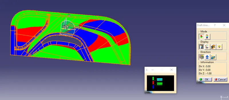
- Select the Draft Analysis to the ClOSED SURFACE.
- Select the Axis and place the Axis line along the Tooling Axis direction.
- Select the Draft angle degree as 3Deg minimum.
- Selected the Surface and found in Green Colour in all the surface area in the Draft Direction.
- Checked the inversion of Drafting to the Core side and Cavity side.
- Cross checked the angle of draft at all surfaces and found that is more than 3 deg.
- Checked the Draft Angle as 1.5Deg for the Dog House Exterior in the Tooling Axis direction.
- Checked the Draft angle as 0.48Deg that is approx to 0.5Deg for the Heat Stakes and Locators are clearing the Draft Analysis in the same Tooling Axis Direction.
- Now Changed the Compass to the Side Core Tooling Axis and activated it.
- Checked the Draft Analysis for the Interior of the Dog House clearing the minimum of 0.5Deg of Draft Angle.
3 DIMENSION PART AND ORIENTATIONS:
- Front View
- Side View
- Top View
- Isometric View