Week 9 - Project 1 - Door Trim Lower with Engineering Features
Report on draft analysis of class A surface as well as the soild model of door trim lower and creation of heat stakes and locaters on it.
Aim: To create a solid model from the given Class A surface of door trim lower and adding engineering features to it.
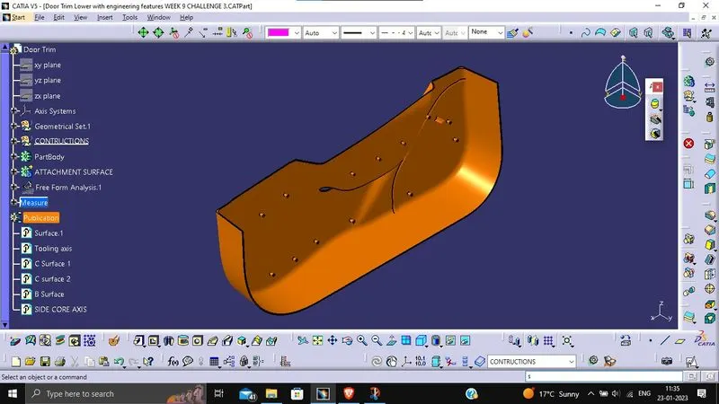
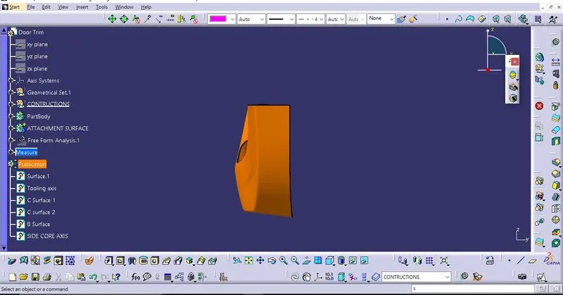
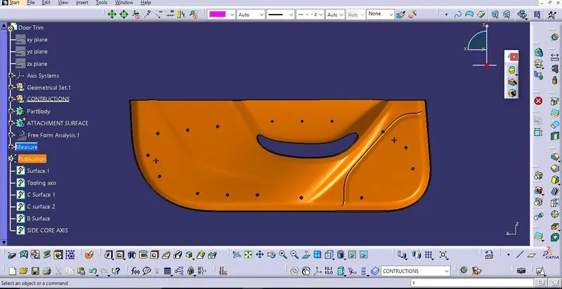
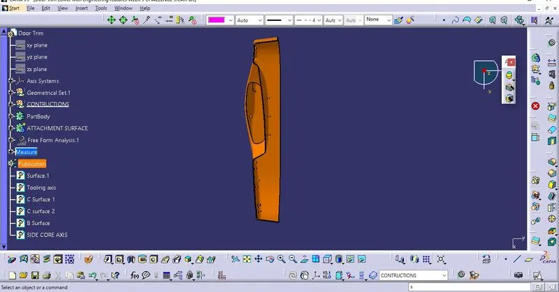
Given Class A surface:
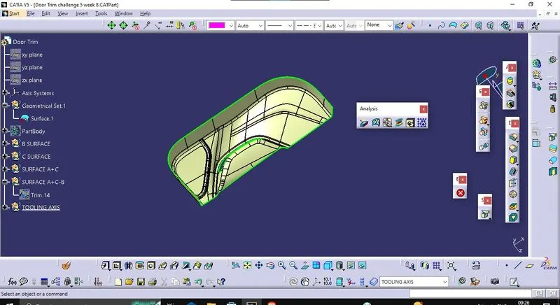
Step 1: Check the connectivity of the A surface ensure that there is no gap between the component.
Step 2:Finding the tooling axis of the component. The tooling axis is nothing but the mould opens or cavity opens. Check the best possible tooling axis. among the three axis z axis is best possible tooling axis.
First create the dummy tooling axis, by creating a line passing through the centre of pocket hole.
Creating the tooling axis by bisecting method: First create a bisecting line between two opposite face of the class A surface by creating the intersection of Class A surface with the plane of artificial axis system , now create another line with proper draft angle with the third single surface. After creating both lines again create a line which bisects both line which are formed previously, the resulting line would be our main tooling axis.
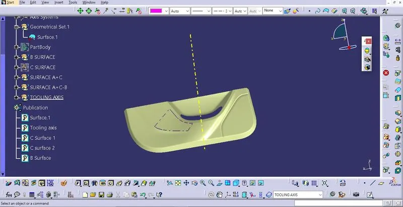
Now perform the draft analysis through the draft analysis toolbar in the bottom. after opening the draft analysis toolbar drag the compass on the tooling axis, click on the lock symbol after compass is aligned.
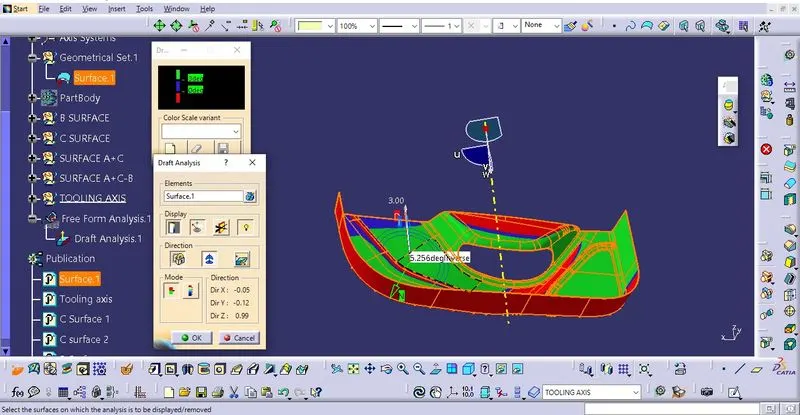
Step 3: Now create Class B surface
First offset the given class A surface to give proper thickness to our solid model, Now use the multiple extract one by one by dividing the offset surface into different patches. Now extrapolate the surfaces by creating the boundaries around them, then use trim command to make a single surface Finally trim that surface with the extrapollated wall to get the B surface and Finally Give the appropirate fillet radius. To complete the class B surface.
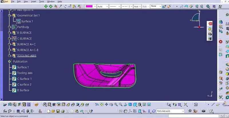
Step 4: Now create Class C surface
To create Class C surface we use Sweep command on the Class A surface by first creating the boundary over the surface and extracting it, after extraction we give Curve smooth command fot smoothening the command. Now use the sweep command and create Class C surface with reference Surface as Class A surface and guiding curve as smooth curve with the draft angle of 3 deg.
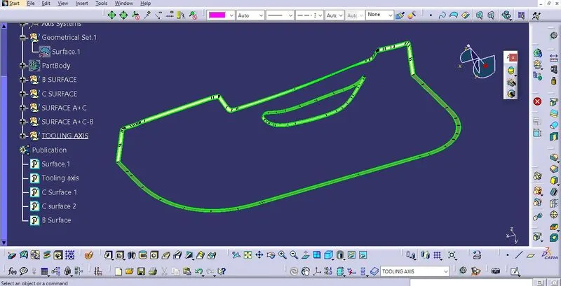
Finally, trim class A and C first then trim with class B surface, remove any irregularities if we face any difficulty in the trimming. Publish Class A, Class B and C surface and tooling axis by using publication command on the tools menu.
Close the surface created from Class A, B and C by help of close surface command on the part design.
Perform the draft analysis on final soid model.
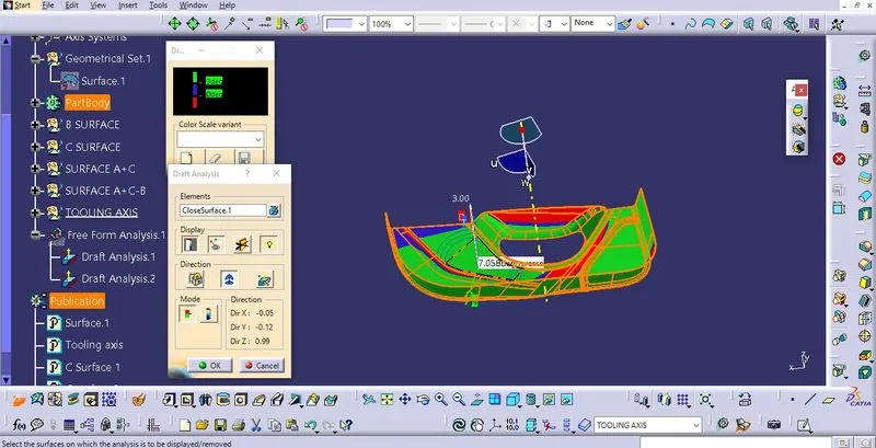
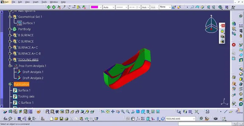
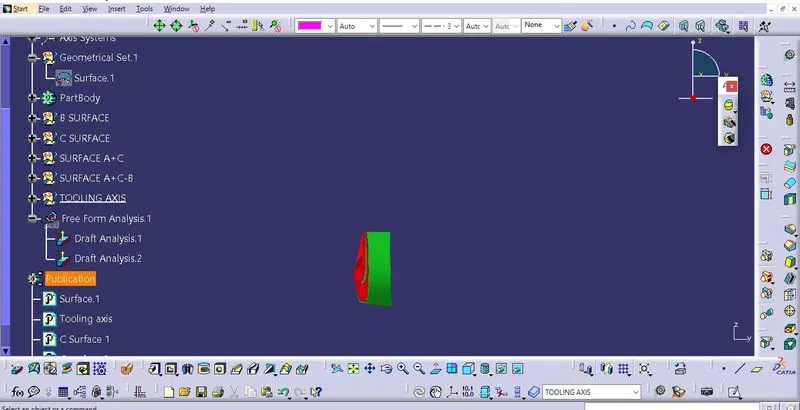
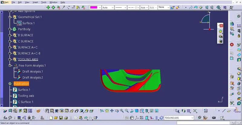
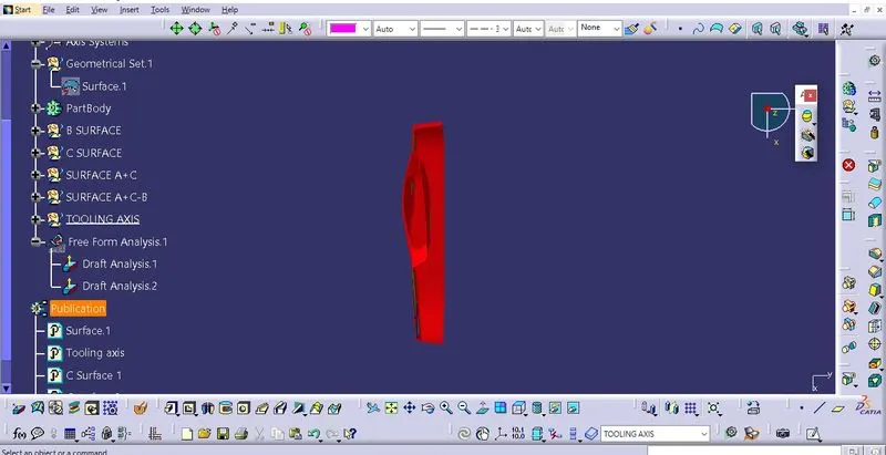
Step 5: Now add engineering features such as heat stakes and locaters with design rules as shown:
We apply 3-2-1 principle to create locaters and heat stakes. So 3-2-1 principle say that in order to completely specify the position in a space of a three dimenional object (such as cube as shown), we refer to six coordinates with total 12 degrees of freedom.
1. Translational position along the X- axis
2. Translational postion along Y axis
3. Translational position along Z axis
4. Rotational position about X axis
5. Rotational position about Y axis
6. Rotational position about Z axis
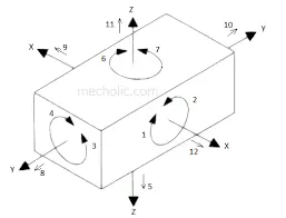
so total we have 6*2 =12 degrees of freedom therefore to resrict the movment of body all 12 degrees of freedom must be restricted.
To restrict the movement of attachment surface along X and Z axis we create 4 way locaters and heat stakes to restrict its movement along Y axis.
4 way locaters: we create them by pad and adding 3*45 deg chamfer, egde fillet of 3mm and all other fillet of faces as 0.3mm with 0.5 deg of draft.
Heat stakes: we create total 16 heat stakes by creating pad such that outer dia is 7mm and inner dia as 5mm and drafting its outer surface by 0.5 deg.
Now create clearance surface by removing the pad such that 4 way locaters have side gap of 0.1 mm with the clearance surface and heat stakes have gap of 0.5mm with clearance surface as shown below :
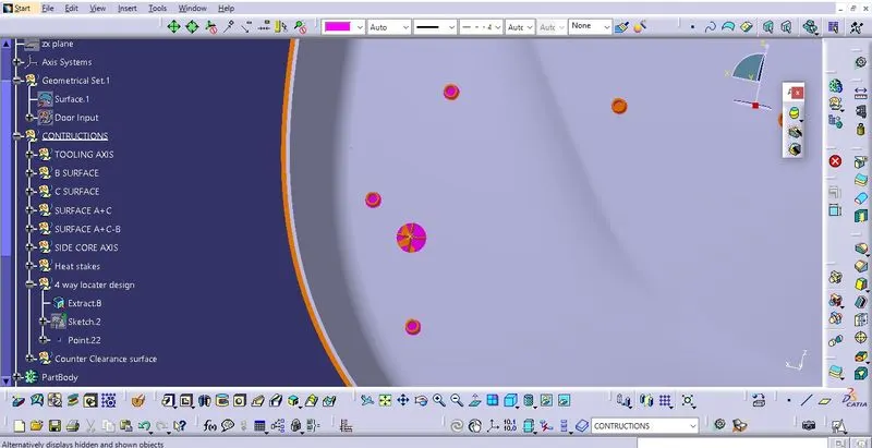
Now do the draft analysis on the final model as shown:
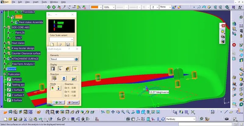
All green areas showing the draft og 0.5 deg which means that our constructed engineering features are clearing draft so our design is proper.
final model: