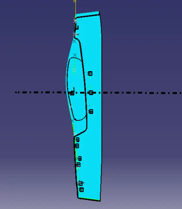
Week 9 - Project 1 - Door Trim Lower with Engineering Features
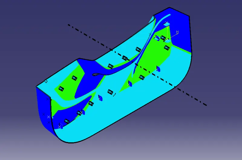
Creation of solid component of door trim lower using given Class A surface and adding engineering features like 2 way , 4 way locators and heat stakes to the Door trim lower and performing draft analysis to the final component.
Door trim lower: An interior component attatched to the inner side of the door. This product will merely improve the appearence to the vehicle interior.
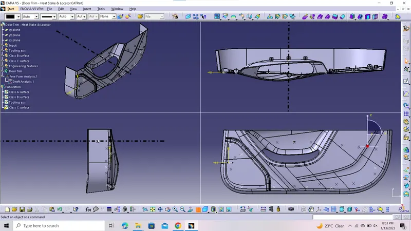
Important terminologies:
- 2 way locators: A 2-way locating pin restricts motion along 1 axis (or 2 degrees of Freedom), like a round pin in a slot.
- 4 way locators:A round locating pin located concentrically in a hole is a common application of a 4-way pin, and helps to further secure the piece.
- Heat stakes: Heat staking also known as thermoplastic staking is the process of joining two dissimilar materials together. In heat staking we use local heating and cooling to raise the temperature of plastic components and allow plastic reforming to be carried out.
1)Steps to be followed to create tooling axis:
- Initially, confirm the surface through which the tooling axis to be passed and extract the surface.
- Create a point on the surface and offset a plane on that point and make an intersection of class A surface using offseted plane.
- Make 2 lines about the 2 walls and make a bisector and the bisector itself is the tooling axis.
2)Steps to create class B surface:
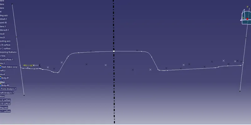
- Offset the class A surface to distance of 2.5mm inwards .
- Make sure that there is no incomplete patches within the surface .
3)Steps to create class C surface:
- Create the boundary all along the edges of the class A surface.
- Using sweep command, create surface along the boundary along class A surface.
4)Initially, join the Class A and Class C surface and trim with Class B surface.
5)Changing to part design work bench, create the soild pf Door handle using its suface model.
6)Steps to create 2 way and 4 locators and Heat stakes:
- Create the points where, the locators needd to be located.
- Place a plane on to the point and make sketch of profile and extrude by changing it to part workbench.
- Copy and paste special within the part and translate it through out the points.
- Initially, assemble it to a part and unitrim it to the door trim.
- Give a draft of 0.5degree all the walls.
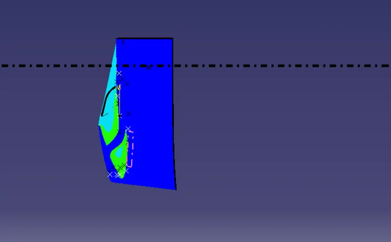
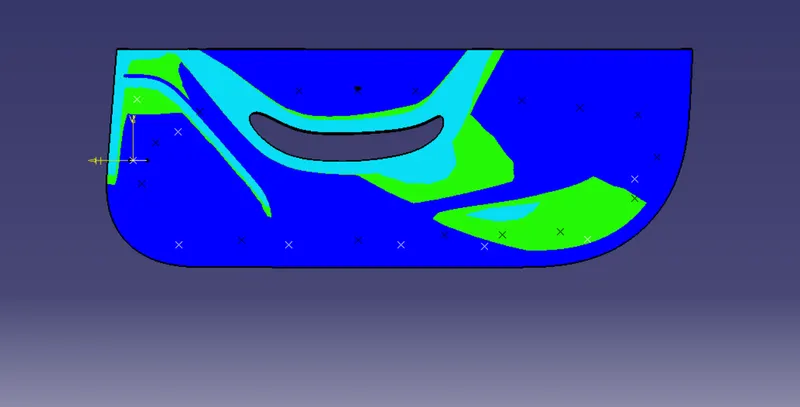
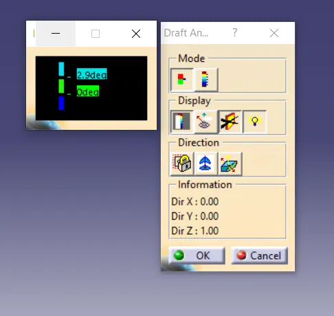
8)Steps to do draft analysis on final out product :
- ON the draft anlaysis and change the material mode.
- Place the coordinate system on the tooling axis.
- Select the component that needed to be analysed.
- Repeat the similar steps to perform the Draft analysis to class A surface.
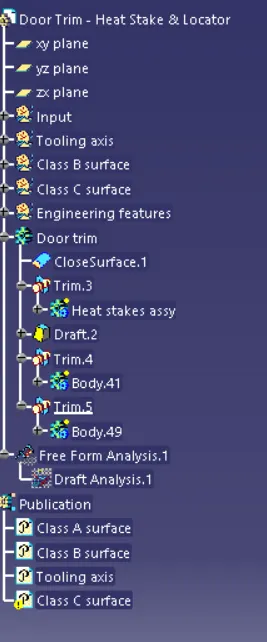
9) Publish Tooling axis, Class A , Class B , Class C surfaces for ease of accesible.