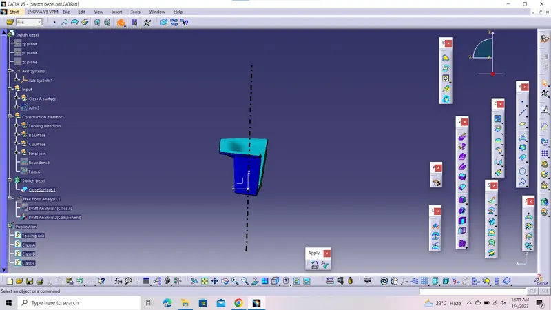
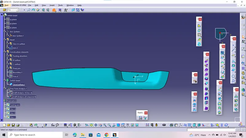
Week 8 - Challenge 2 - Switch Bezel Design
Creation of solid model of Switch bezel component using its Class A surface and to perform Draft analysis on Class A surface and also on Final output solid switch bezel.
Switch bezel:Switch Bezels in car are parts which contains switches and controls for different functions like Window control, Door lock/Unlock,Media and Temperature controls.
Steps followed to create Tooling axis:
- Check the best possible side to create the tooling axis.In maximum case, we consider the bin type area to be were the tooling axis is to be passed through.
- So, here we can say that the Tooling axis is passing through the bin type projection , through the base .
- initialy, we extract the base surface and place a point on the centre of the extracted surface.
- make a intersection curve with reference to the point on the surface.
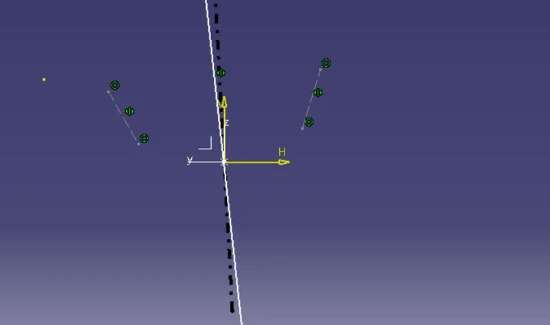
- Draw 2 line aling 2 side walls facing opposite to each other.
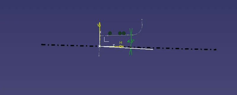
- Make a bisector with 2 lines and draw a line passing through the reference point with aligning at an angle of 4 degrees with the wall adjacent to the opposite one.
- Make another bisector with this line with the 1st bisector.
- 2nd bisector itself is the tooling axis of the model.
1)Steps followed in this project to create Class B surface:
- Here, the class B surface, is created by extracted induvidual patches from the class A surfaces and untrim it , followed by extrapolet and ofseting it to a value of thickness of 2.5mm
- Trim according to the Class A surface.
- Make sure , there is no gaps between the surfaces within B surfaces
2)Steps followed in this project to create Class C surface:
- Class C , in this project is created by extracting boundary edges of class A surface , make boundary with curvature continuity.
- Using sweep command , taking boundary curve as reference in along to draft direction at an angle of 3 degree create a surface along the edges of Class A surface.
3)Make sure, that the meeting edges osweep surface is not overlapping.If it occurs, then extrapolet the edges , that is overlapping .
4)Join the Class C and Class A surfaces
5)Trim the Class C and Class B surfaces.
6)Ensure that there is no gap between the surfaces.
7)Create a part body, With the command THICKNESS , make the surface model to solid model.
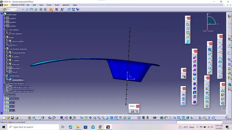
8)Steps to do Draft analysis on Switch bezel and its Class A surface:
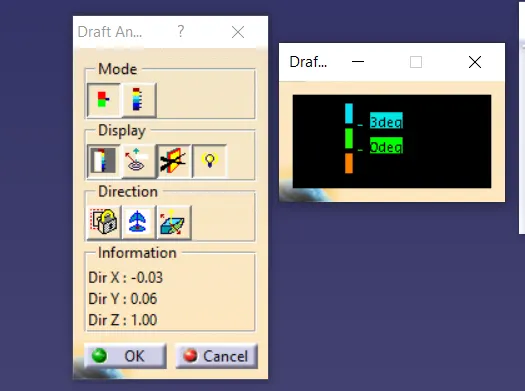
- Select the angle range 0 to 3 degree with proper color code.
- Place the coordinate system on to the Tooling axis, which means we are arranging a coordinate system for drafting anlaysis.
- After proper arranging of coordinate system , lock out the view.
- Select draft option , and select the Solid switch bezel
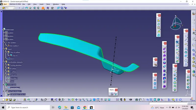
- Same, above mentioned steps, are used to perform the draft anaylsis for Class A surface.
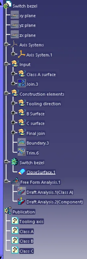
9)Publishing of Tooling axis, Class A suface, Class B surface and Class C surface is also done for easy accessible.