Photo Realistic Rendering
PROJECT 1:
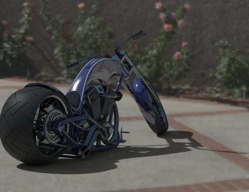
PART MODELLING, ASSEMBLY AND PHOTO REALISTIC RENDERING OF AMERICAN CHOPPER
- OBJECTIVE:
- To do part modelling of American chopper part wise using solidworks software.
- Assemble the complete chopper and to do Photo realistic rendering in the solidworkds software itself.
- To do the modelling with the help of Blueprints.
- To gain knowledge of american chopper partwise and its assembly.
- INTRODUCTION:
Hello everyone,
I'm Shiju. I'm a mechanical engineer.I will discuss about the design methodology of American chopper, partwise and its assmebly and its photorealistic rendering using Solidworks software.
Here both surface modelling and solid modelling are adapted.
The listed below are the parts of American Chopper that neede to modelled and assembeled followed by rendered using solidworks software.
- Transmission Belt
- Kick stand
- Front-fender
- Rear fender
- Chain
- Oil tank
- Pedal
- Front wheel
- Rear wheel
- Front fork
- Chassis
- Engine along with exhaust manifold
- Gas tank
- DESIGN APPROACH:
Here we model each par(SLDPRT) seperatly and do assemble in seperate file(SLDASM) , so this approach is said to be Bottom - up approach.
UNIT:-1
- FEATURES AND TOOLS USED FOR MODELLING OF AMERICAN CHOPPER.
1.Boss Extrude:One of the most basic and handy tool that is used to convert 2d sketch to 3d solid.
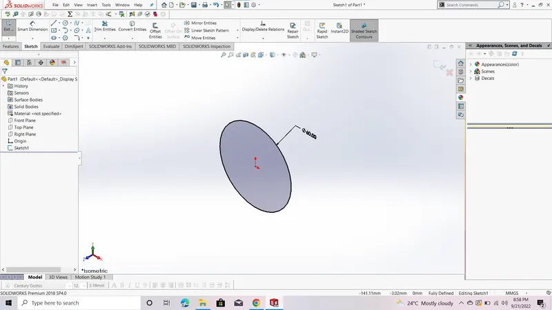
Before boss extrude
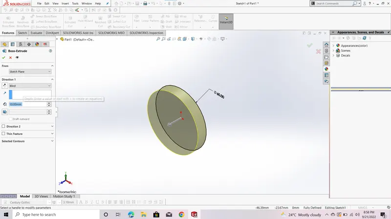
After boss extrude
2.Revolve Boss/Base:One of the most basic and handy tool that is used to convert 2d sketch to 3d (CYLINRICAL/SPHERICAL)solid.
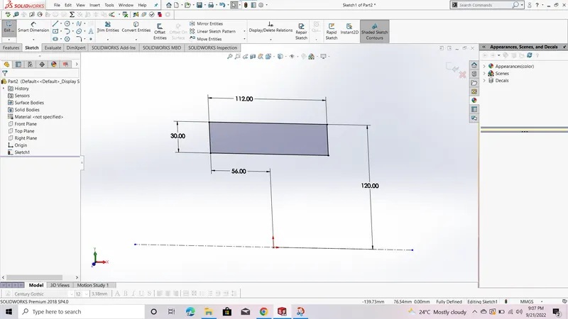
Before Revolve boss
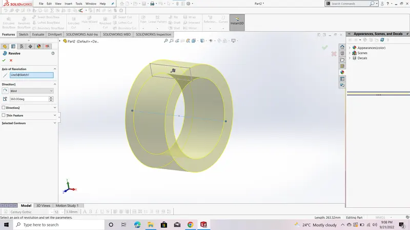
After Revolve boss
3.Circular pattern:It is the handy tool , used for repeat the any 3d feature in angular direction.
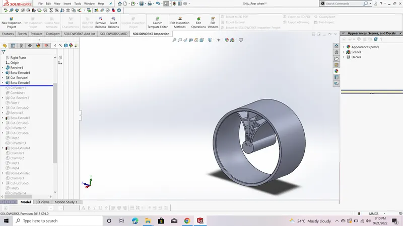
Before Circular pattern
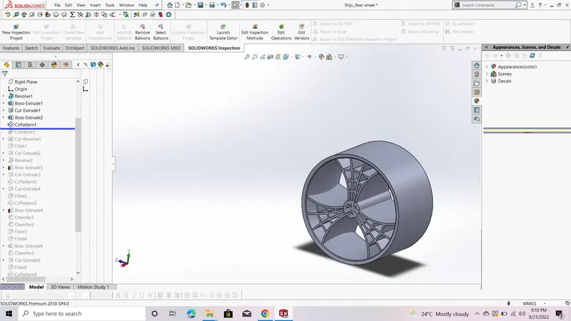
Before Circular pattern
4.Dome:It is one of the handy tool used for creating elliptically shaped bulged out type surface.
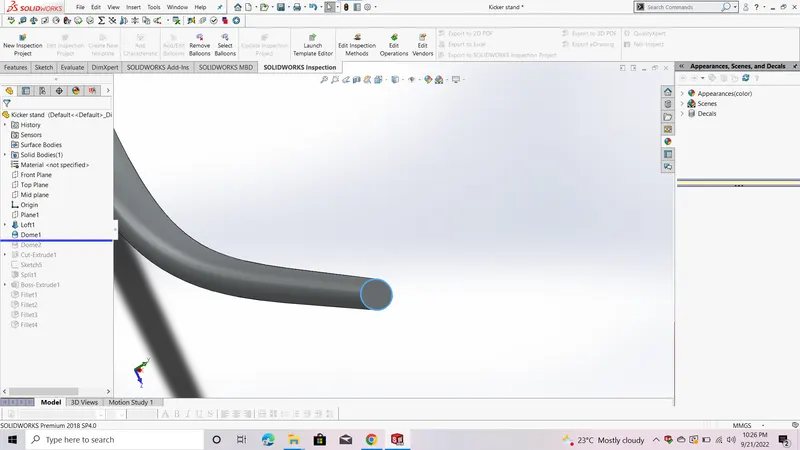
Before dome
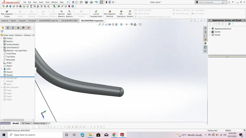
After dome
5.Fillet:It is used to create the round surface at sharp edges .It has 4 options:1)Constant size fillet 2)Variable size fillet 3) Face fillet 4)Full round fillet.
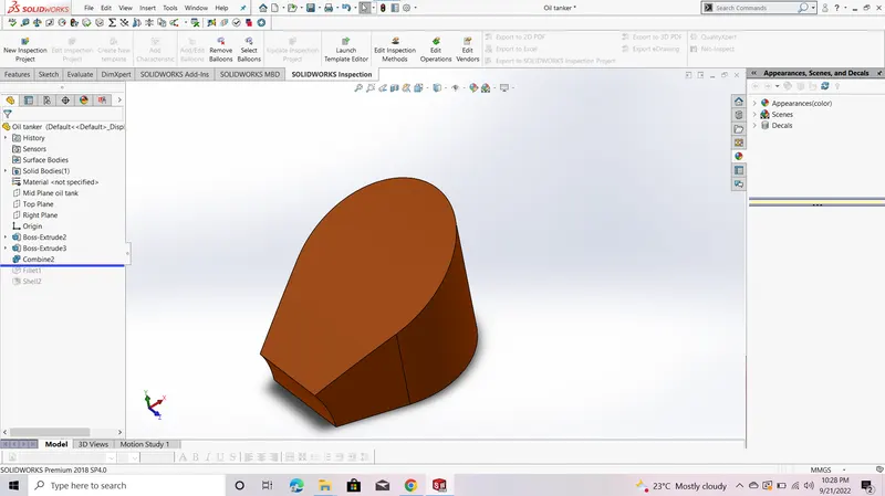
Before Fillet
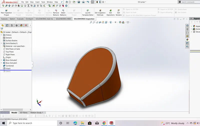
After Fillet
6.Extrude cut:It is used to remove the material on/from solid.
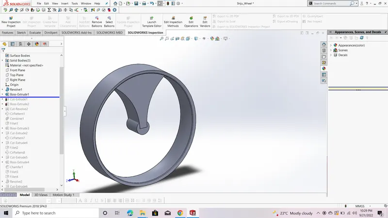
Before Extrude cut
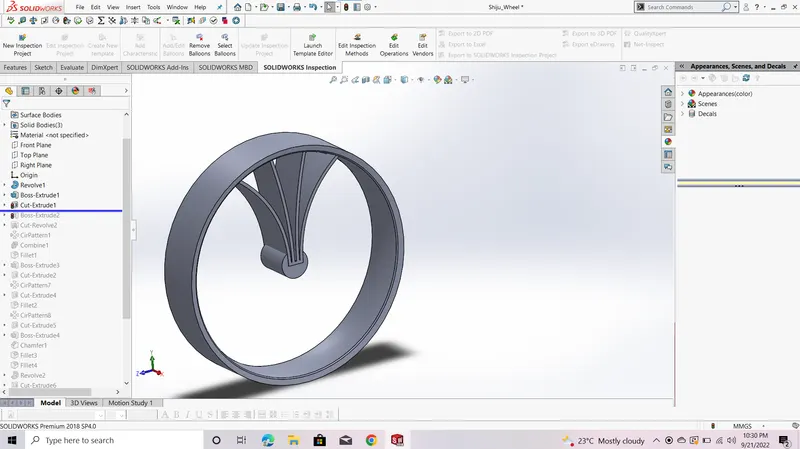
After Extrude cut
7.Shell:It is used to convert the solid body to shell type body.
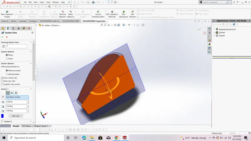
Before Shell
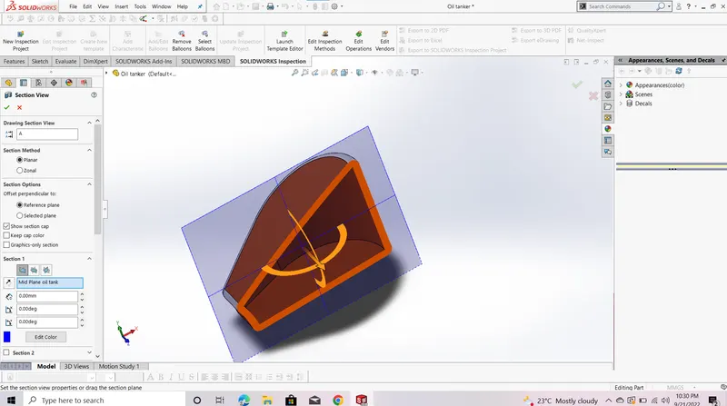
After Shell
8.Linear pattern:It is the handy tool , used for repeat the any 3d feature in linear direction.
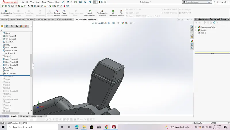
Before Linear pattern
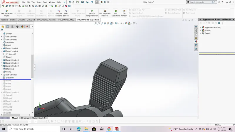
After Linear pattern
9.Mirror:It used to create a copy of solid about an plain/axis.

Before Mirror
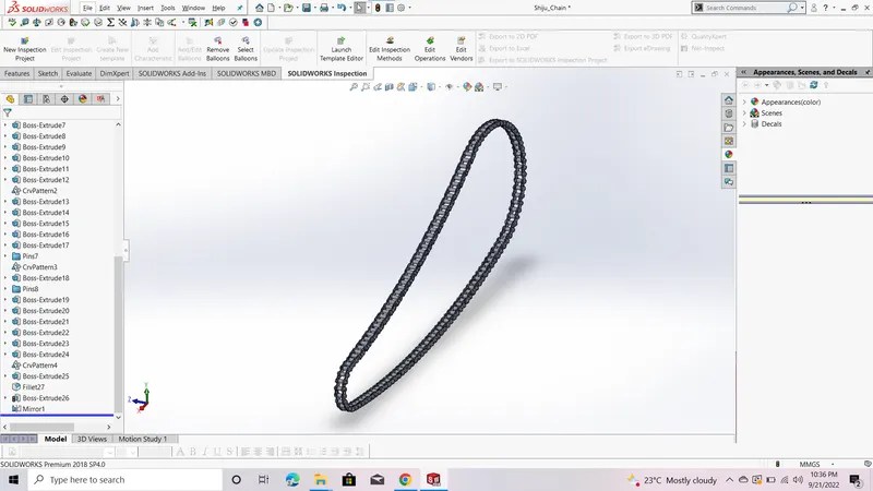
After Mirror
UNIT:-2
Details of parts used in American chopper assembly
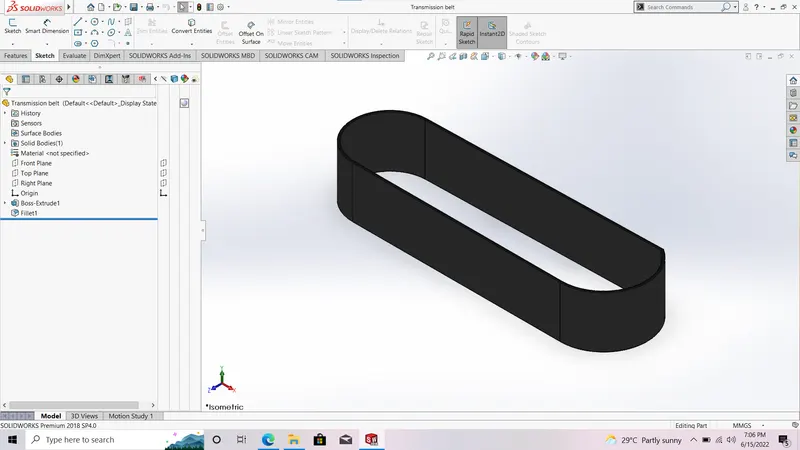
1) Transmission Belt:
It is used to tramsmit the power from drive wheel to driven wheel.
The commands used to model the transmission belt are
- Boss extrude
- Fillet
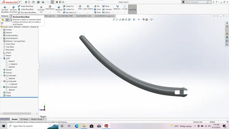
2)Kick stand
It is used to support the bike in rest condition.
The commands used to model the Kick stand are
- Loft
- Dome
- Extrude cut
- Split
- Boss-extrude
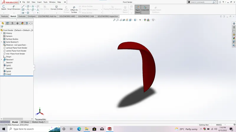
3)Front fender:
It is used to cover the front wheel and to protect the rider from mud splited from front wheel.
The commands used to model the Front fender are
- 3 Point arc
- Revolve
- Split
- Fillet
4)Rear fender:
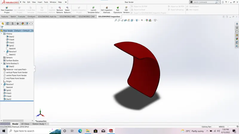
It is used to cover the rear wheel and to protect the engine from mud splited from front wheel.
The commands used to model the rear fender are
- 3 Point arc
- Revolve
- Split
- Fillet
- Shell
5)Chain:
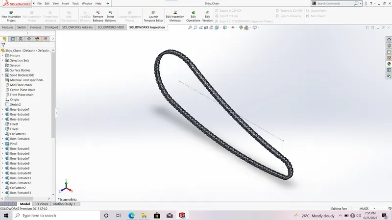
It is used for transmission from engine to rear wheel.
The commands used to model the Chain are
- 3 point arc
- slot
- boss extrude
- Blocks
- Curve driven pattern
- Mirror
- Fillet
6)Oil tank:
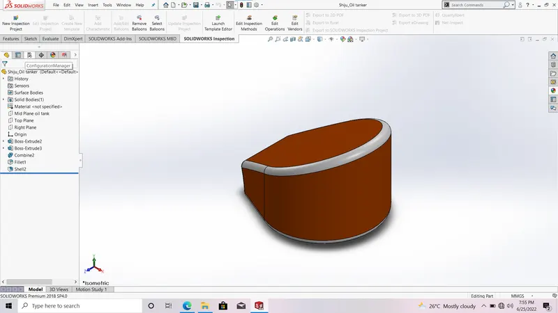
It is used to store oil.
The commands used to model the Oil tank are
- Boss extrude
- shell
- fillet
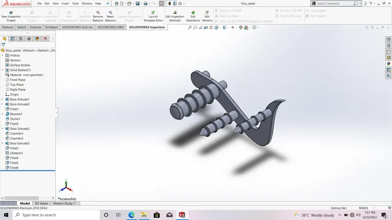
7)Pedal:
It is used to place foot of the rider while riding
The commands used to model the Pedal are
- boss extrude
- revolve boss
- dome
- fillet
- chamfer
- linear pattern
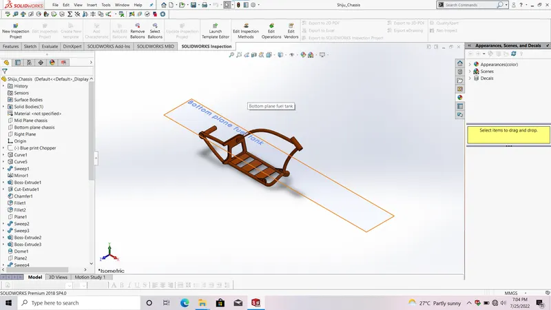
8)Chassis
It is said to be the skeleton of chopper.
The commands used to model the Chasis are
- Sketch picture
- project curve
- sweep
- mirror
- fillet
- chamfer
- dome
- split
- linear pattern
- combine
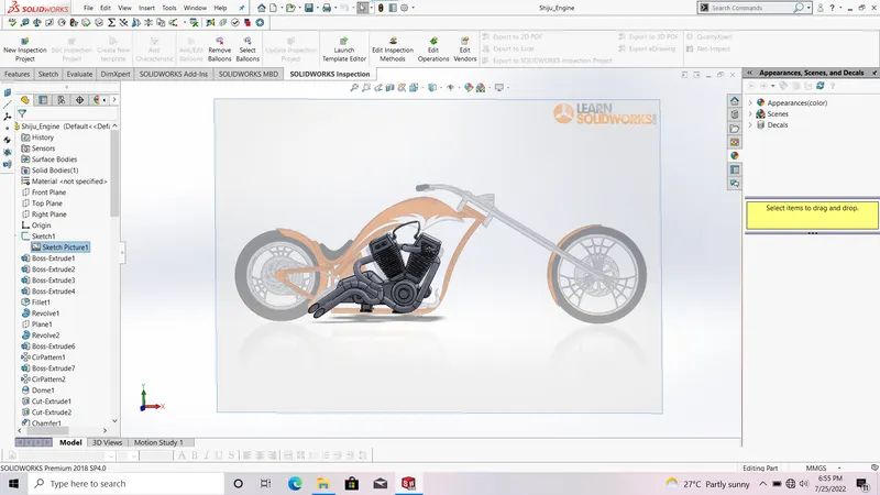
9)Engine with exhaust manifold:
It is said to be the heart of vehicle.
The commands used to model the engine are
- Boss extrude
- fillet
- revolve
- refernce plane
- circular pattern
- dome
- extrude cut
- mirror
- linear pattern
- split
- sweep
- composite curve
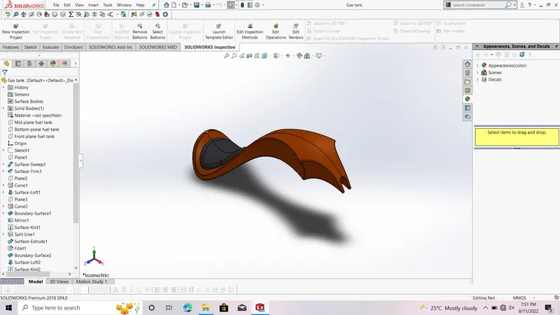
10)Gas tank:
It is used for store fuel/gas in chopper.
The commands used to model the Gas tank are
- Surface loft
- boundary surface
- mirror
- split line
- Refernce plane
- Surface extrude
- knit
- fillet
- swept cut
- shell
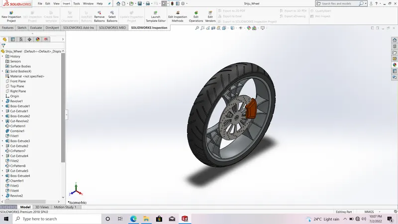
11)Front wheel:
The commands used to model the Front wheel are
- Cut xtrude
- Circular pattern
- revolve
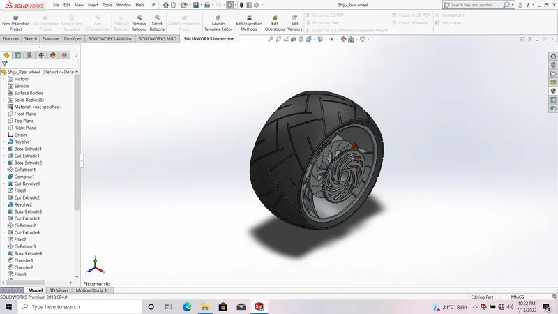
12)Rear wheel
The commands used to model the Rear wheel are
- Cut xtrude
- Circular pattern
- revolve
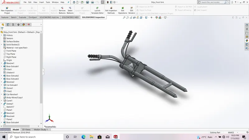
13)Front fork
The commands used to model the Front fork are
- revolve
- projected curve
- boss extrude
- mirror
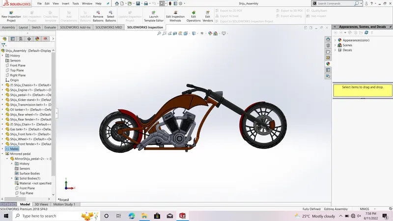
ASSEMBLY:
Assembly is the final assembled part of all above mentioned parts.Here as mentioned earlier we adopted bottom- up assembly approach.
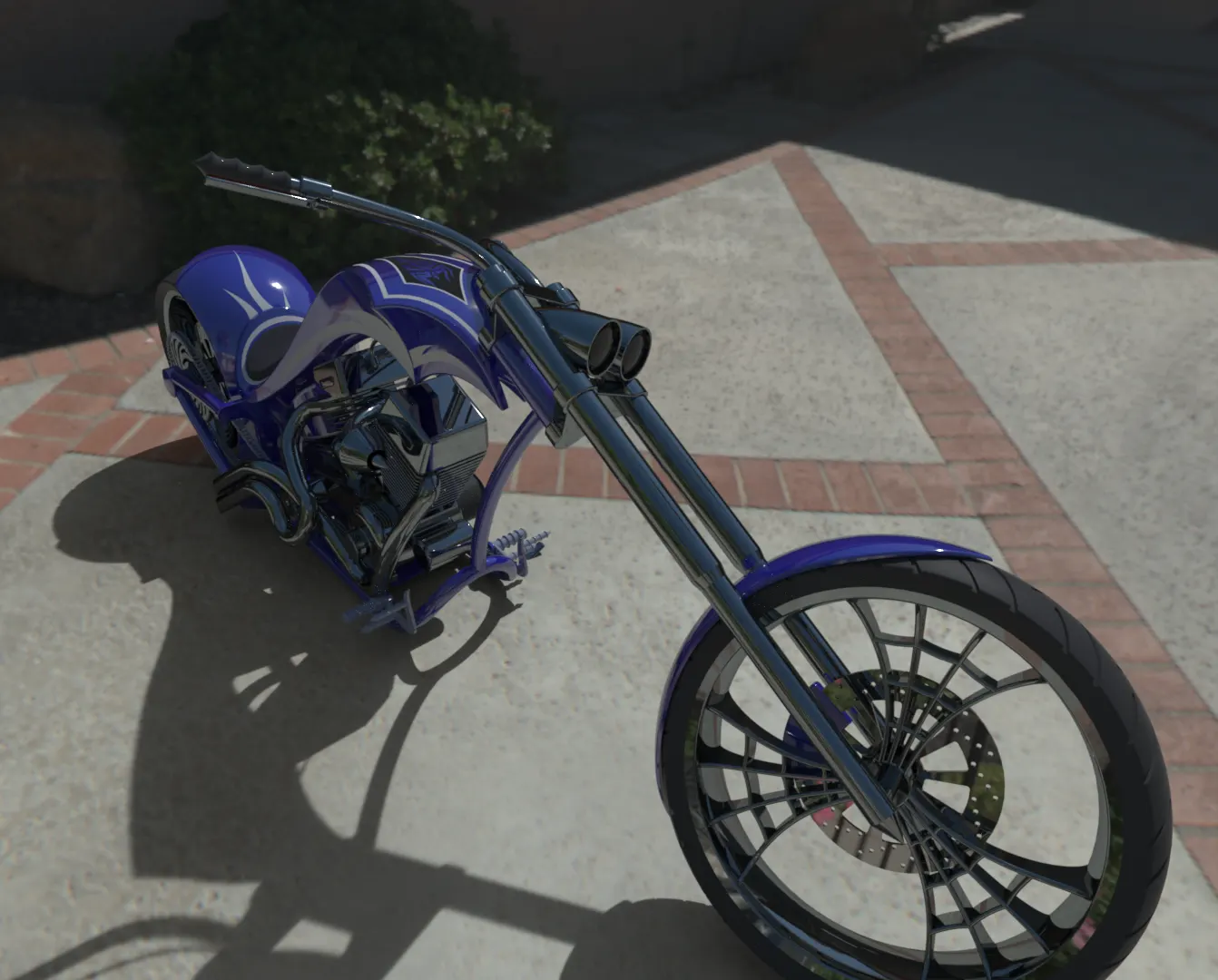
RENDERING
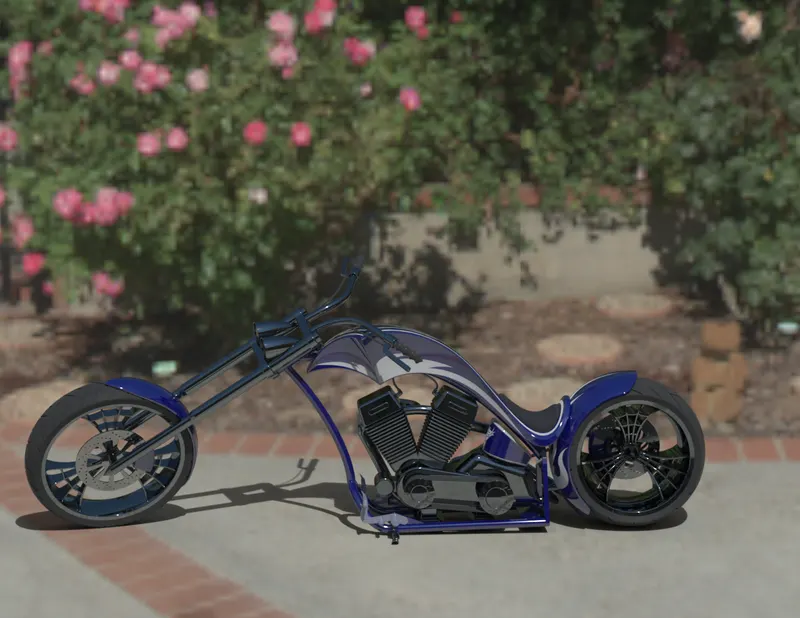
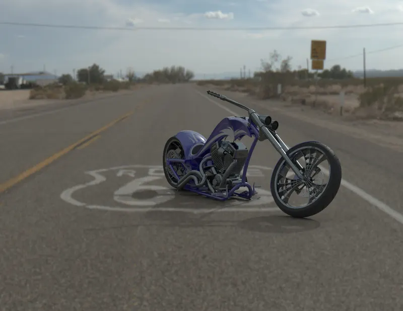
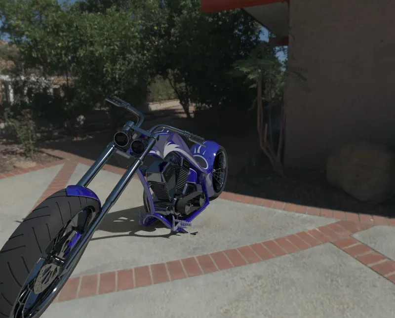
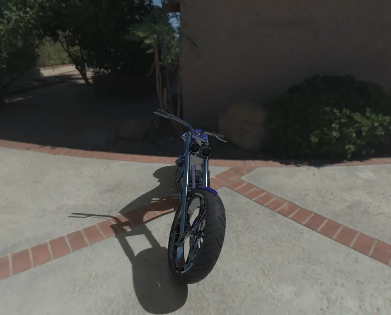
Rendering is the photo realistic appearence of assembled american chopper.
Thank you