Week 8 - Challenge 3 - Coin Holder Design
Title: Creation of soild model of coin holder using its Class A surface and also performing draft analysis on coin holder.
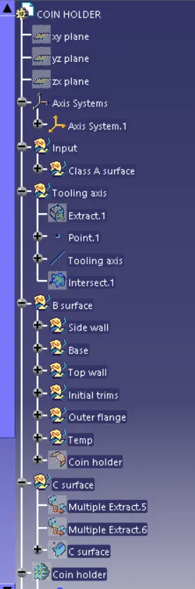
Steps followed to create tooling axis:
- In this particular , the major portion of model is bin area and so we conclude that the tooing axis will pass through this bin area .
- next after , we extract the bottom base surface of that bin, hide the Class A surface except the extracted surface .
- Here , in this particluar model, we found that, wall that is adjacent to the base surface is perpendicular and therfore we cannot perform bisecting line method here.
- Hencefourth, we can conclude that the line passing through the centre of base surface itself is the tooling axis .
- place the point on the centre of the surface and place the coordinate axis on that point.
- Make a line that is passing through that point.
- Make sure that , this all are done in a seperate geometrical set named tooling axis.
Steps followed to create Class B surface:
- Initially, make a clarity on the surfaces that which is filleted region and which is flat area and make identical using shading with different color.
- Extract the flat surfaces from the Class A region , offset it to a value of thickness of 2.5mm and perform Untrim , Extropolate and trim the surfaces.
- Give the appropriate fillets by considering thickness.
- Make sure that the create surface have only single boundary , by using boundary command.
- Make sure this all are done within seperate geometrical set named Class B surface and publish it.
Steps followed to create Class C surface:
- Extract the outer edges of the Class B sufaces and make sure the curves have tangent continuity.
- Using sweep command, create a suface using edges of Class A surfaces along Class A surface at angle of 90 degrees to class A surface.
- Publish this surface also
Now join the classA and class C surfaces and ensure there is no gap between the surfaces.
Trim the Class B surface with joined Class A and C surfaces.
Ensure there is no gap between any of the surfaces
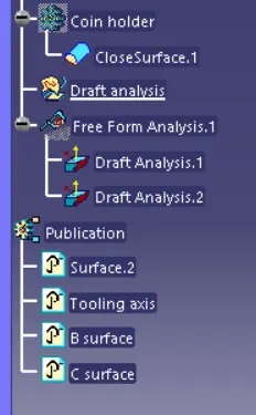
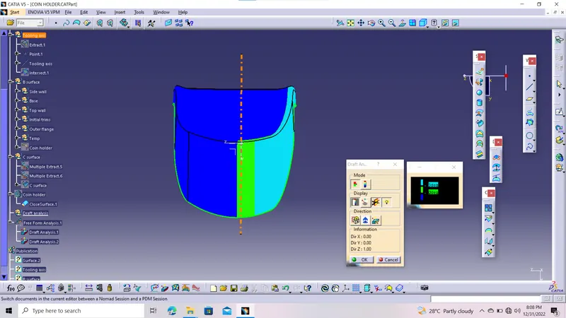
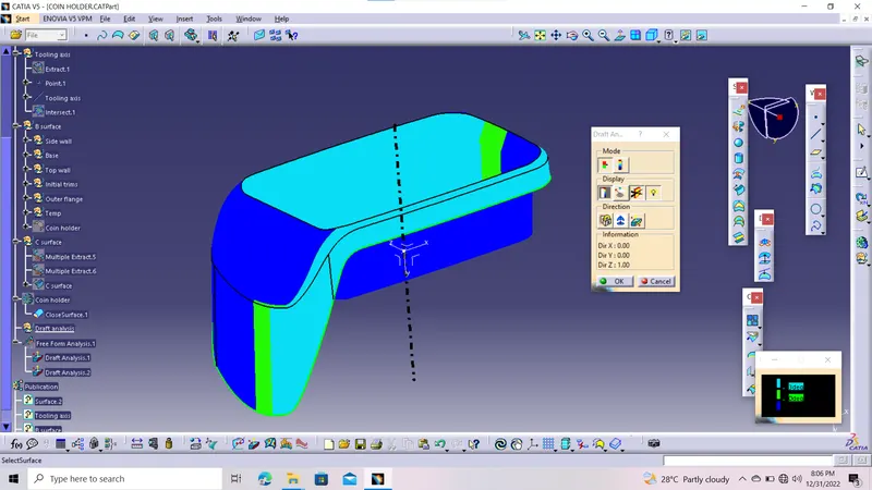
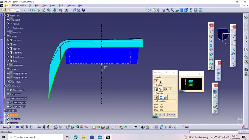
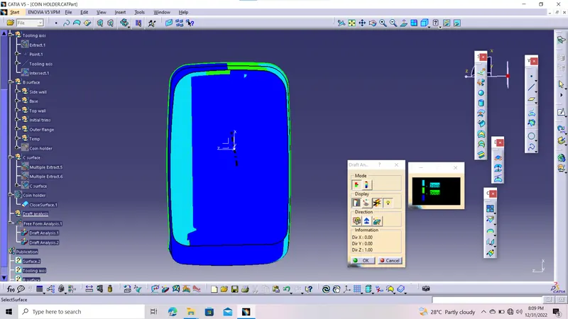
Steps followed for performing draft analysis:
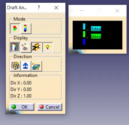
- Set the draft angle and color ranges for different angle range.
- intially place the coordinate sysytem on to the tooling axis .
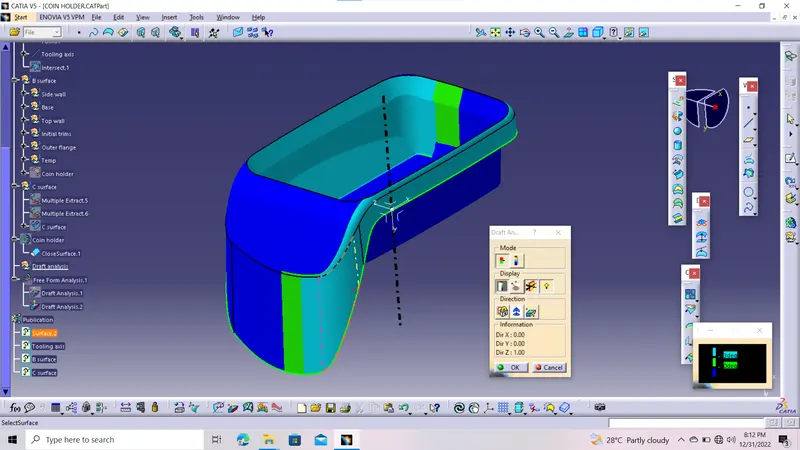
- Perform the draft analysis for Class A surface .
- Change the material
- Then after , perform the draft analysis on the created component.
- The component will be displayed with different color ranges.
- If we need to know the exact angle values, then place the cursor on the surface, it will show the angle value at the particular point.
Those are the steps, that i adopted to create the coin holder and to performed draft analysis on coin holder.