Week 8 - Challenge 1 - Base Bracket Design
Creating solid model using given CLASS A surface of base bracket and also t do draft analysis on base bracket.
Major terminologies:
- Draft analysis: This is a kind of analysis made on a part. By draft analysing we can judge the created part is easily removable from core and cavity or not. This analysis is based on color ranges.
- Tooling axis: The tooling axis is the direction in which the core and cavity opens.The 1st and foremost step for a design enginer is to create tooling axis from given class A surface.
- Class A surface: Styling or class A surface is the terms used in plastic product design . Class A surface is smooth (aesthetic) or visible to outside.
- Class B surface:This is said to be engineered surface since all engineered characteristics and features are found on this class B surface.
- Class C surface: This is the joining sirface between class A and class B.It is the thickness of the plastic component.
- Draft angle:It is the angle that is provided on the side ends or surfaces that are exposed to side walls of core and cavity in order to assure the smooth ejection of molded plastic component from core and cavity
Key points to be considered while creating Tooling axis:
- Connectivity between the surfaces.
- No existance of gap between and within the surfaces. If there is any gap, then solid formationis impossible.Tis can be cross checked by using boundary command
Steps to create tooling axis:
- Check which is the possible side to create tooling axis.
- Place the point on the circle and place the axis system on that point to make it clear.
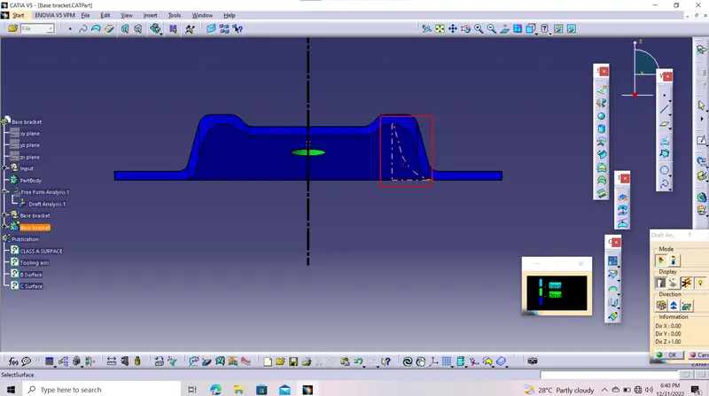
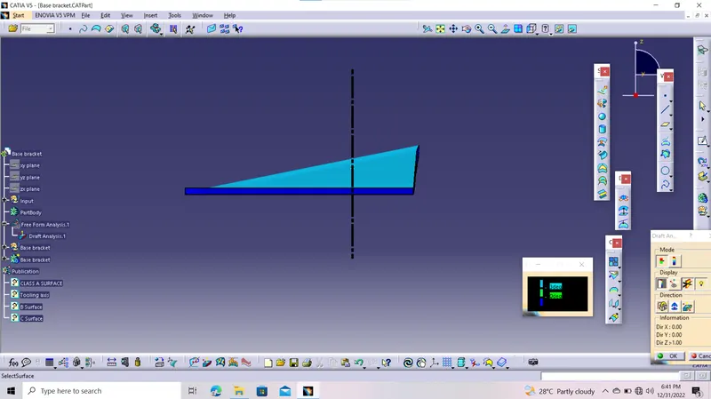
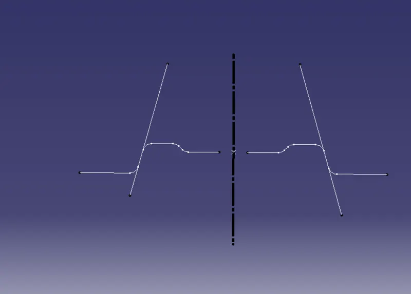
- Create an intersection curve along YZ plane.
- Make 2 lines along intersection curve as shown below.
- Make a bisector with 2 intersecting line by projecting point.
- The bisector itself is the tooling axis.
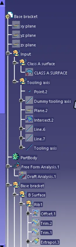
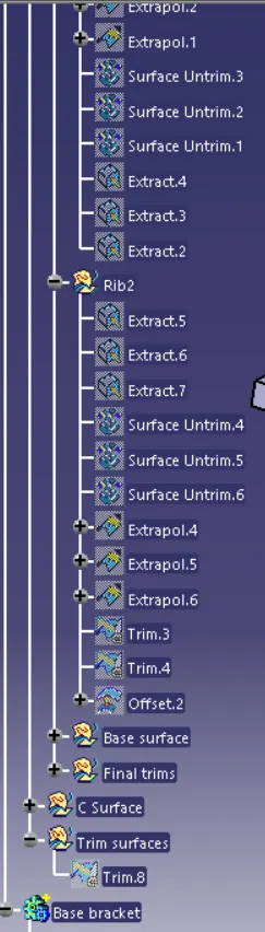
- Here , class B is created by extracting , offsetting to a thickness of 2.5mm distance and trim to get replica of Class A.
- Class C is created by a boundary of Class A and using sweep command along Class A.
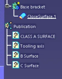
- After the class C and class A creation is completed , join them together , then after the joined surface is trimmed with class B surface.
- Then after , the surfce model is converted to soild , in part model work bench using thickness command.
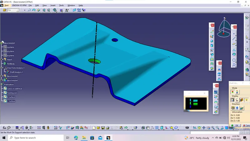
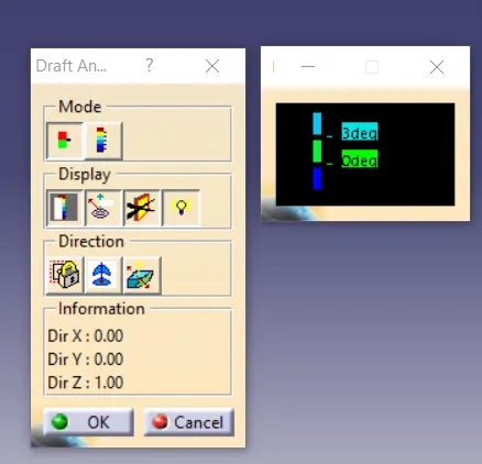
- Then draft analysis is permoed on creted model, with changing material mode with minimum of 0.5deg.
- Set the range of draft angles.
- From the dialoge box, click the coordinate system and bring the coordinate system onto tooling axis. This means we are providing a coordinate system to draft.
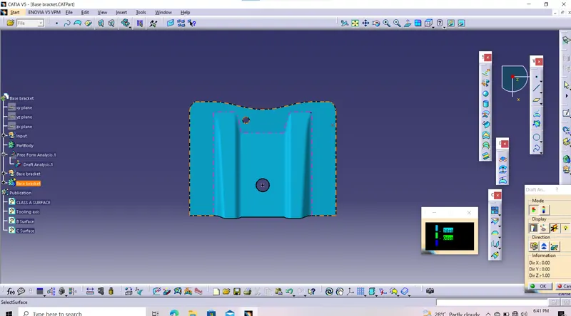
- Then after , select the component that to be analysed. Then selected body will appeares in color range as according to draft angle range.
- We can check the angle at any surface of the body , by placing cursor on the surface that needed to be finded .
In this manner, I modeled the base bracket and did draft analysis on the base bracket.