Week 9 - Project 1 - Door Trim Lower with Engineering Features
|
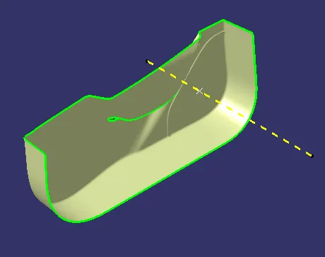
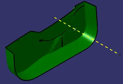
AIM: To create the Door Trim Lower plastic component through the given class-A surface meeting the draft angle requirements. To create Heat Stakes and Locators considering relevant design rules and conducts the draft analysis on the final component. Check the given input: Before proceeding with the design of the component, the first step will be to check the given input surface (class-A surface) for any discrepancies if any in the form of discontinuity in the surface or any open contours which may pose a restriction while designing the component. This can be done by using either of the ‘boundary’ or the ‘join’ feature in the ‘Generative Shape Design’ workbench and then through visual inspection. Creating Tooling Axis: After checking the input surface, a suitable tooling direction has to be created based on which the features of the component rely upon such as the draft angle. The tooling direction helps to analyse if the component can be easily manufactured and ejection from an injection mould without any restrictions. The tooling axis is usually created using the ‘Bisection’ method but here it is created by a line drawn normal to the surface of the given class-A in the y-direction.
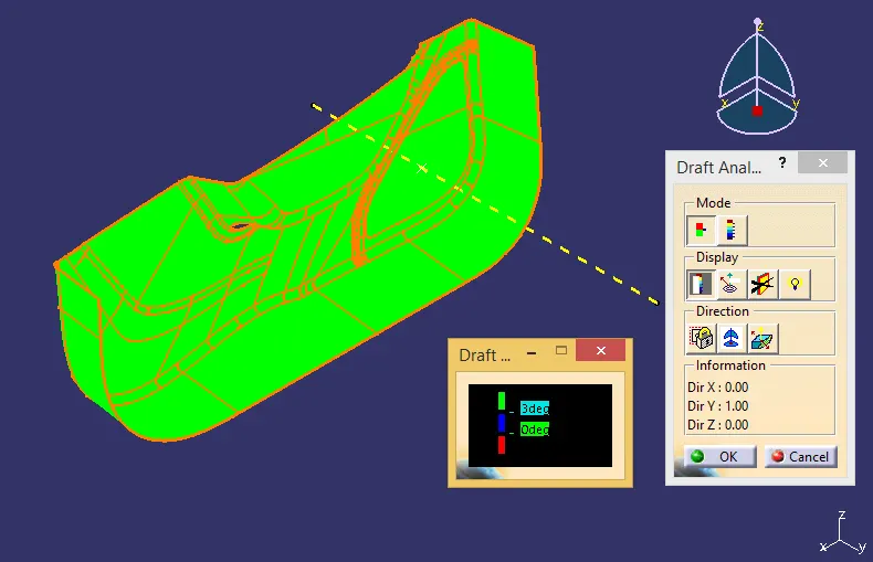
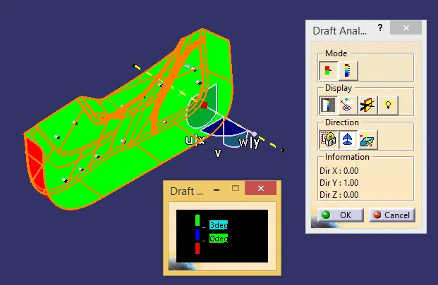
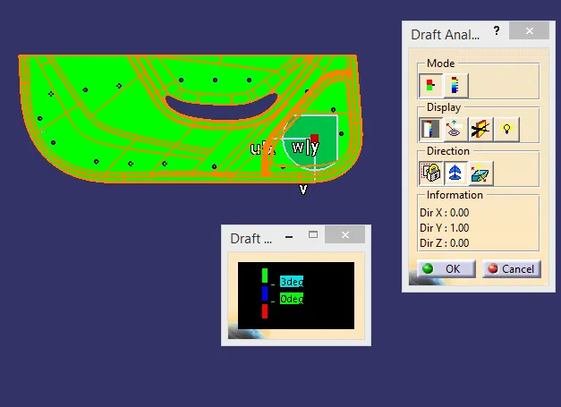
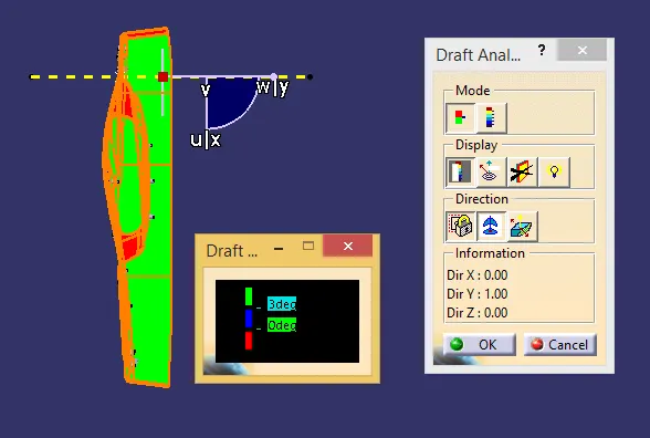
Draft Analysis on class-A: Draft analysis on the given class-A surface is carried out in the ‘Generative Surface Design’ workbench under which the ‘Customize View Parameter’ is set to the ‘Material’ mode. Then from the ‘Inset’ tab, ‘Draft analysis’ tool is selected from the ‘Analysis’ section and then the required draft angle is set with respect to the tooling axis created and the draft analysis is carried out.
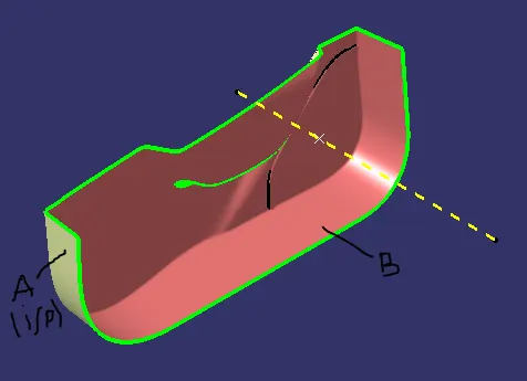
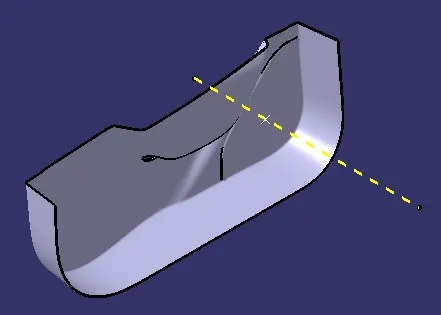
Creating class-B Surface: In this case, the class-B is created by just using the offset feature on the input class-A in its entirety to a value equal to the thickness of the component. Due to computing errors some of the edges of part of the surface fail to offset to the required value. There missing parts of the surface can be solved using the ‘fill’ or the ‘multi-section solid’ options from the workbench.
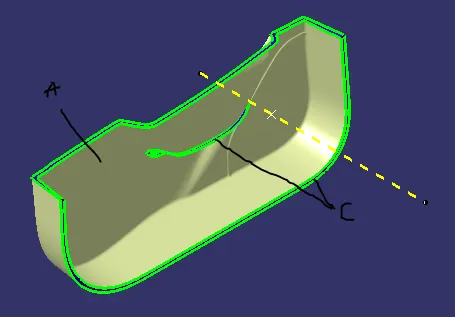
Creating C surface: Then the C surface is created by extracting the edge surface of the given class-A and then using the ‘sweep’ command the C surface is created giving relevant angle with respect to the Tooling Axis. This operation can be done in parts as it may not be possible to sweep the entire outer surface at once. Later all the fragments of the C surface are joined together either using ‘join’ or ‘trim’ option.
Creating Solid CAD Component: First the input surface and the class-C surfaces are added together and the protruded portions if any are trimmed off. Then the class-B surface is trimmed off from the previously obtained surface and then all are joined to form a closed surface of the component. This closed surface is filled using the ‘close surface’ feature from the toolbar to obtain the required solid CAD component.
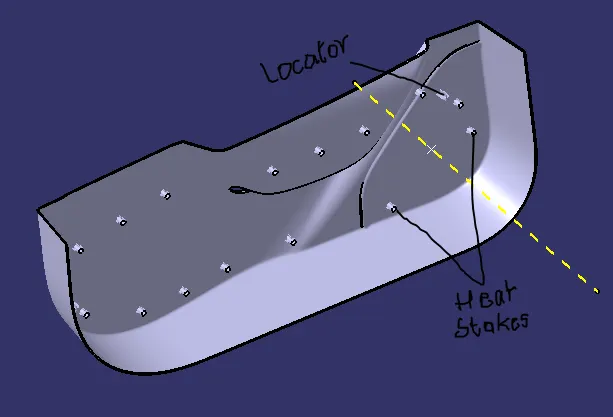
Creating Features (Heat Stakes and Locators): First the locators are created by extracting a reference surface from the input surface and then at a suitable point the sketch (positions sketch) for the locator is created. Then this sketch is thickened using ‘Pad’ option from the ‘Part Design’ workbench inside a new body. Then the locator is given relevant features such as draft, chamfers etc. Since multiple locators are required, the body of the created locator is copied and ‘paste special with link’ option is used to create similar body of the locator. Then this new locator is translated to the required position on the component. Later the locators are added to the component using suitable Boolean operation. Similarly the heat stakes are also created and multiple heat stakes are produced using the initial creation and then ‘paste special’ option and translating it to the required position.
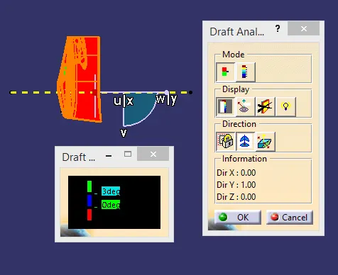
Draft Analysis on final Component: Finally the draft analysis on the overall plastic component is carried out in a similar manner as done on the class-A surface. And for the dog house feature, the draft analysis should be carried out along a different tooling direction as it required a side core to manufacture. So a new side-core axis is created which is perpendicular to the initial tooling axis and similar procedure as above is carried out for draft analysis of the dog house feature along the side core axis.
|