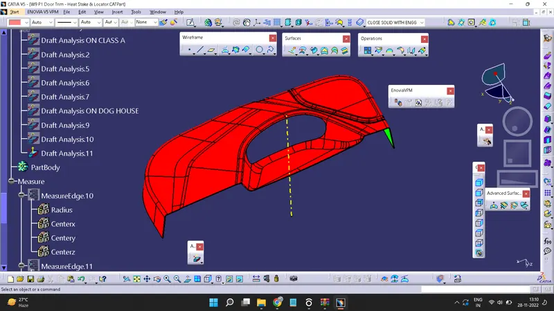
Week 9 - Project 1 - Door Trim Lower with Engineering Features
AIM:
To Create the Door Trim with Engineering Features Component from the given Class-A surface.
To Create the Tooling axis for the given Class-A Surface.
To perform the Draft analysis on CLASS A and the final solid component.
To Create the B Side Feature(Locators, Heat Stakes & Dog House) on the component by following the design rules.
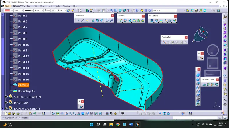
Check CLASS A Continuity:-
Before start working on model must check the model. A model should be enclosed and check surface continuity should be proper. For this check it by using the Boundary.
CREATING TOOLING AXIS -
The next step is to create the tooling axis for the part which will determine the direction in which the core and cavity of the mould will move.
The mold is built in two separate pieces, basically. You have a Cavity side and you have the Core side. The Core pulls apart from the Cavity and that's the Dye line or the Tooling Direction.
Designer must ensure that all holes and slots are covered in the main tooling and thus side core must be avoided whenever possible
After analysing visually for the best possible tooling axis, an axis system is created on the centre of one of the surfaces of the door trim.
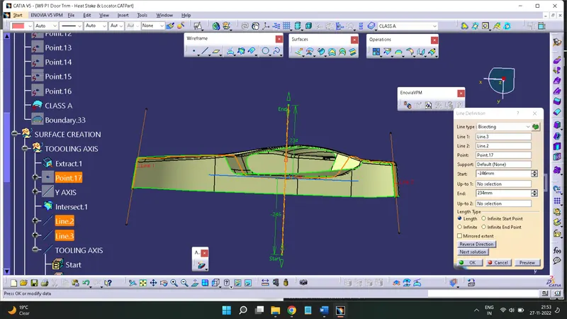
Firstly check the tooling axis in a x/y/z component and the other method for creation of tooling axis in a bisecting Method.
For a bisecting method…
First of all need to analyse a component for best tooling axis
Now Extract a base surface and create a point (by using Point on surface)
Then insert a Axis System on a point.
If our tooling axis is in Y direction then we need to find a tooling axis angle with X & Z Axis.
So Use a Bisecting method for it.
Firstly create a intersection from with class A and XZ plane
and create line in intersection then create bisecting line of these two line.
It will be XZ plane tooling Axis.
This same procedure needs to follow for YZ plane tooling axis
It will be final Tooling axis of component.
DRAFT ANALYSIS:
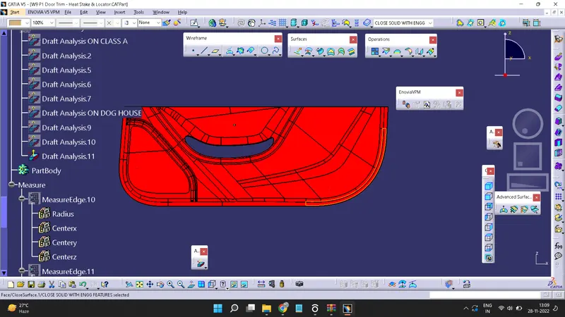
Draft analysis is done on the class a surface after the tooling axis has been obtained
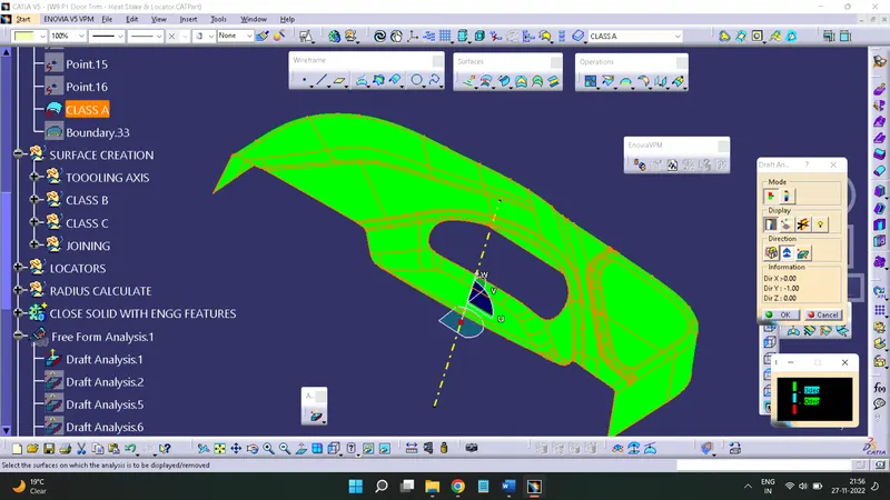
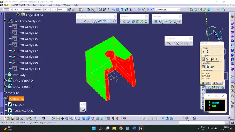
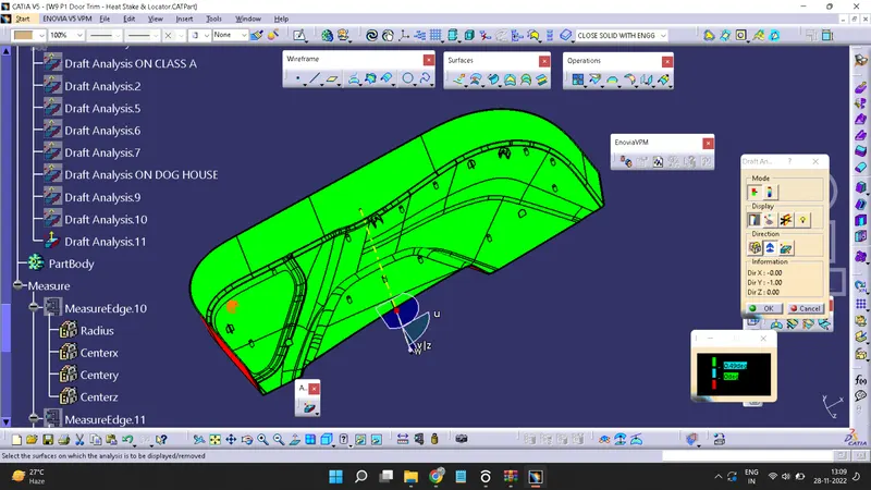
Draft Analysis command enables you to detect if the part you drafted will be easily removed. This type of analysis is performed based on color ranges identifying zones on the analyzed element where the deviation from the draft direction at any point, corresponds to specified values.
The part must have a minimum draft angle of 0.5 degrees on all the tapered faces
Using the feature draft analysis tool and the compass the part surface is validated for the minimum draft criteria
The Before going to drat analysis go to customized view parameter >under mesh >check material and then click ok.
Now for draft analyses go to insert » analysis » feature draft analysis.
Use the compasss to define the draft direction.
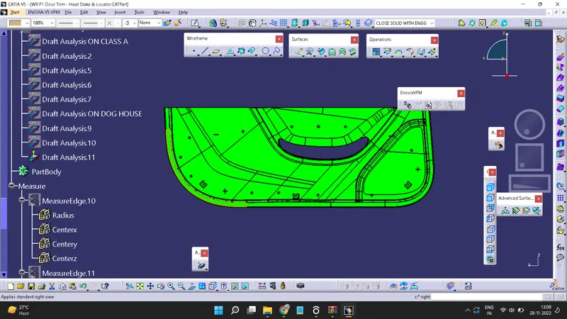
In the colour scale change the draft angle to 3 degree.
The component changes to green in indication of passing draft angle.
Use running point to check the angle on the component.
CLASS B SURFACE
After all the validation has been done, the class B surface is created by offsetting the class B surface to a distance of 2.5 mm
After offsetting many openings in the surfaces are found which are closed with the help of sweep, multi sections-surface and fill command.
Trim the extra surfaces using trim command.
The class B surface is then extrapolated to trim it along with the class C surface
Insert them into new geometrical set and name it with respective part names.
Apply fillets to the model after creating the entire surface.
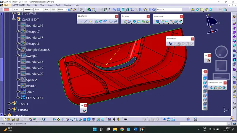
CREATING CLASS C SURFACE
The class C surface which connects the class A and class B surface is created by sweeping the boundary of the class A and using the class A as a reference.
The sweep is divided into several parts in order to avoid complexity
Surfaces which are parallel to the tooling direction are swept with the tooling axis as reference and with a draft angle of 3degrees
Use sweep command > choose profile type line > subtype as with draft direction > choose guide curve and draft direction > draft angle as 3 degree > preview.
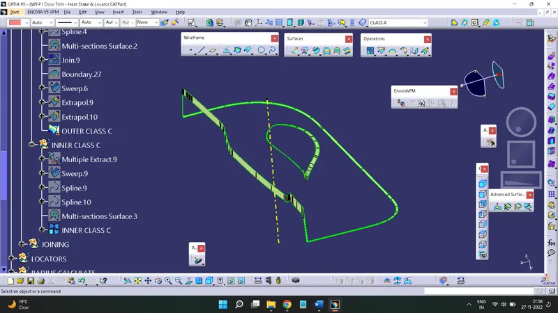
Joining of CLASS A, CLASS C & CLASS B
After getting sweep then trim the output with class B surface to get final output.
The final trim is created by joining the Class A and C surface and finally trimming it with the Class B surface. The combination of class A, B and C surface is then converted into a solid with the aid of fill command in the part workbench
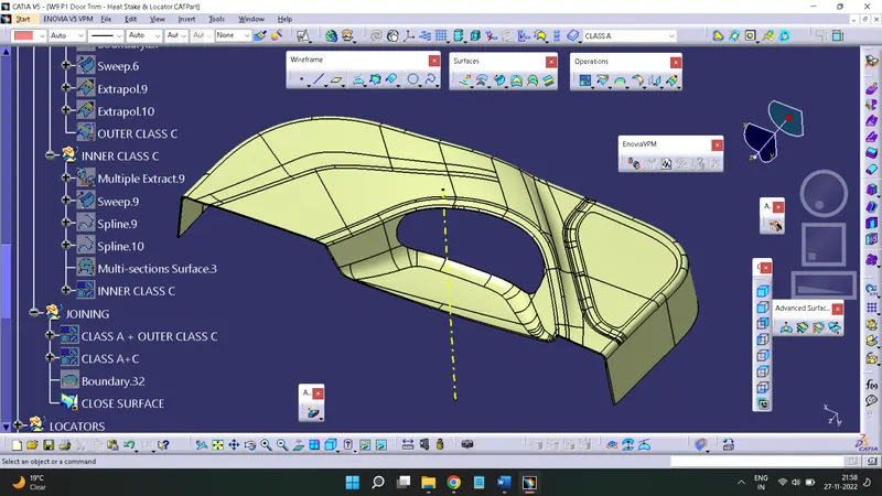
HEAT STAKES & LOCATORS:-
Heat stakes are used to join the two different parts by the method of giving heat in the top tip of the heatstakes, it will melt and deposited in the slot after it will automatically get joined.
Locators are use to arres the degree of freedom , If it a xy,yx based component we will able to arres the x,y freedom
we are having 12 number of degree of freedom so using of locators to lock it.
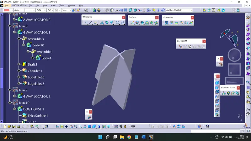
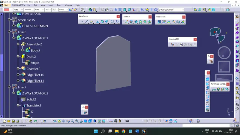
It is having two different types ,they are two way locator and four way locator.
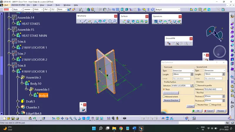
For creation of 2/4 way locators first create a point and create a plane on it.
Now use a positional sketch for create a 2/4 way locators sketch.
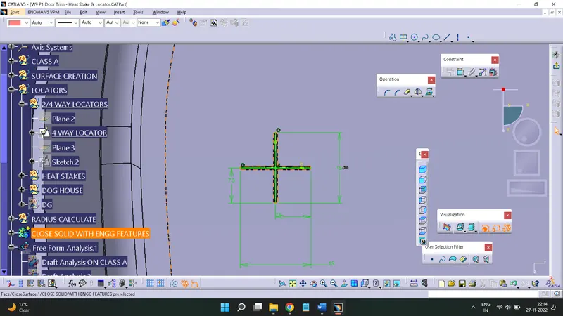
Use a pad for create a solid give it thickness 1mm with neutral Fiber or can give thickness in both side.
Give a draft of 0.5deg with base in tooling direction & do Chamfer the do fillet
Follow thw same for creation of 2 Way Locators
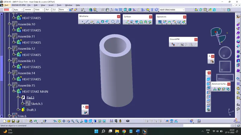
CREATON OF HEAT STAKES:-
For creation Heat Stakes first create a point and create a plane on it.
Now use a positional sketch for create a Heat Stakes sketch.
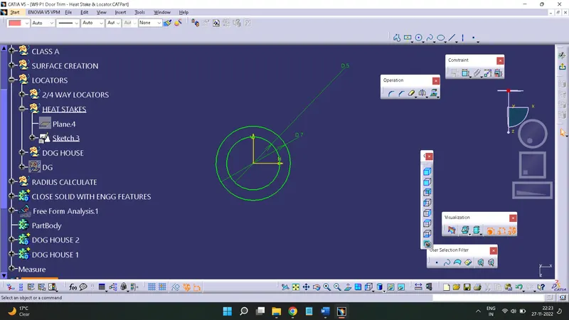
Give a draft of 0.5deg with base in tooling direction & do fillet
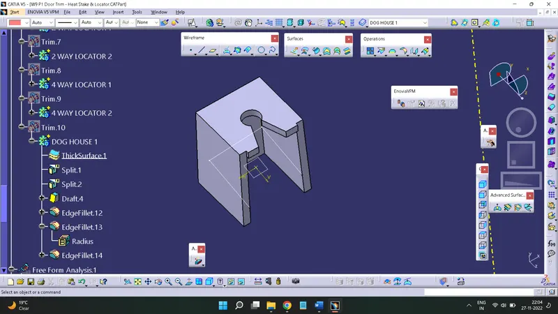
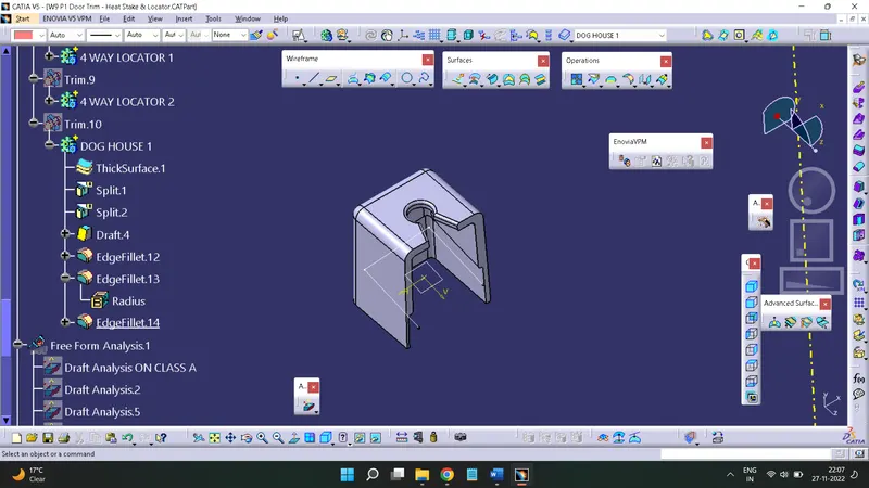
CREATION OF DOG HOUSE:-
The two main purposes of a dog house are to avoid sink marks and to house various other engineering features like screw boss, locators etc.
The dog house should follow certain design rules which are stated below
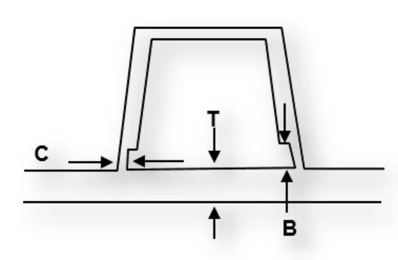
- Doghouse wall thickness at the intersection of the part wall ( C ) should be 40% or less than the main wall stock ( T ).
- The height of ( B ) should be between 3.0 – 6.0 mm
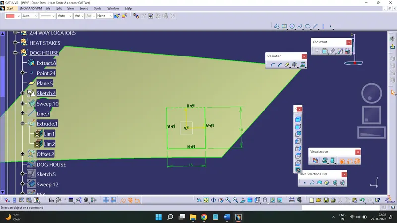
For creation of dog house first create a point and create a plane on it.
Now use a positional sketch for create a dog house sketch
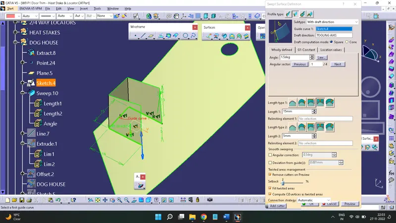
Now do sweep with Profile Type Line & Subtype with draft direction
Select a Sketch & draft direction with 1.5deg angle & choose a Length Type EXTREMUM for both length.
Now Cover the Sweep and Remove a unwanted surface by using trim
And a Dog house Surface profile created
DRAFT ANALYSIS:-
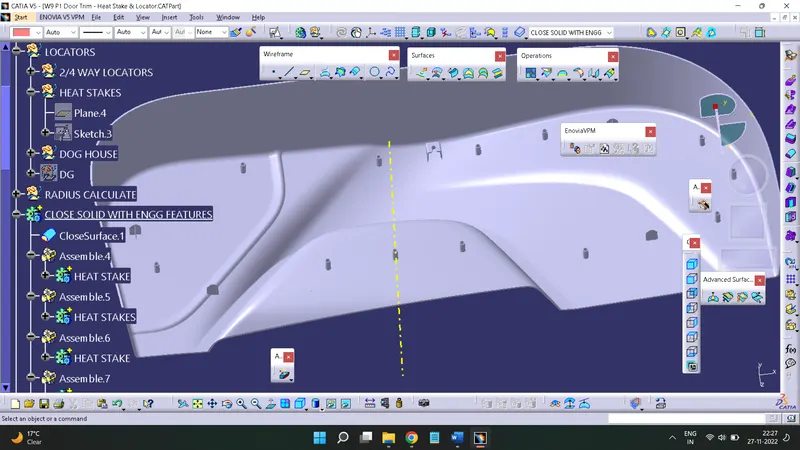
Join all the B side features by using the different-different boolean Operations & get the final component.
FINAL DRAFT ANALYSIS:-
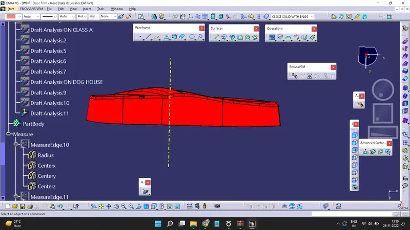
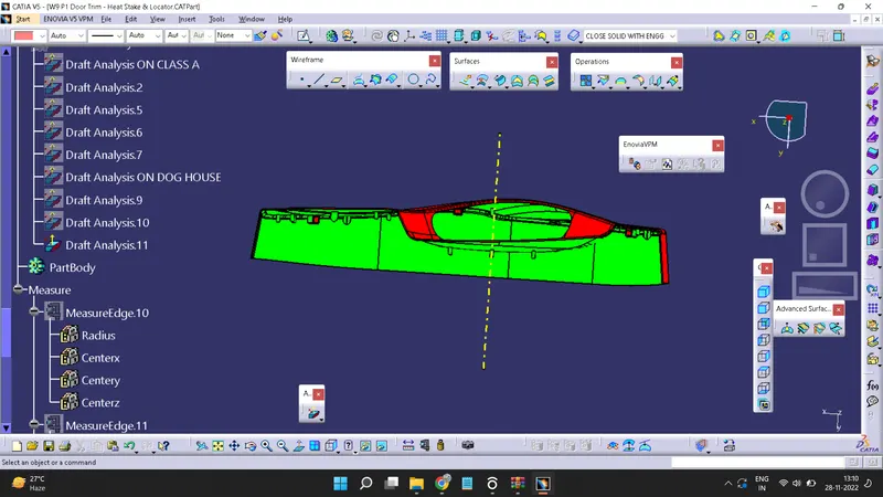
DIFFERENT VUEWS OF DOOR TRIM:-