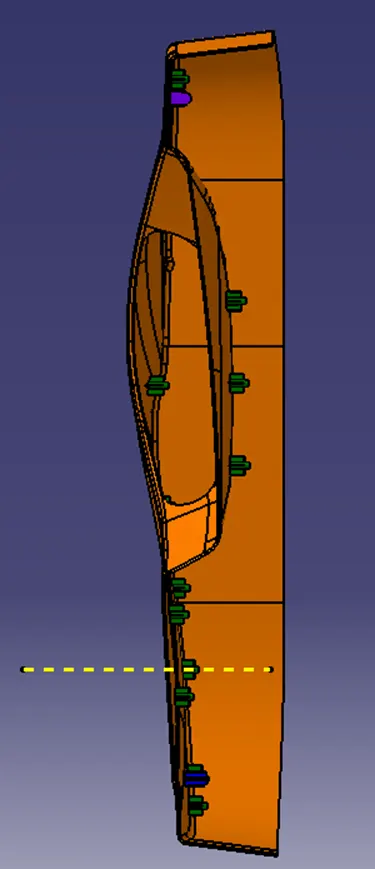
Door Trim Lower with Engineering Features
Title-
Door Trim Lower with Engineering Features
Objective-
- To create the Door Trim Lower Plastic component through the given Class-A surface. To begin with, the tooling axis for the given Class-A Surface should be created meeting the requirements of the draft angle and at the end perform the Draft analysis on the model.
- To create the Heat Stakes and the locators considering the design rules mentioned in the video for the door applique.
Introduction-
The 3-2-1 Locating principle- The 3-2-1 principle of location (six point location principle) is used to constrain the movement of workpiece along the three axes XX, YY, and ZZ. This is achieved by providing six locating points, 3 pins in base plate, 2 pins in vertical plane and 1 pin in a plane which is perpendicular to first two planes.
Degree of freedom controlled by 3-2-1 location principle
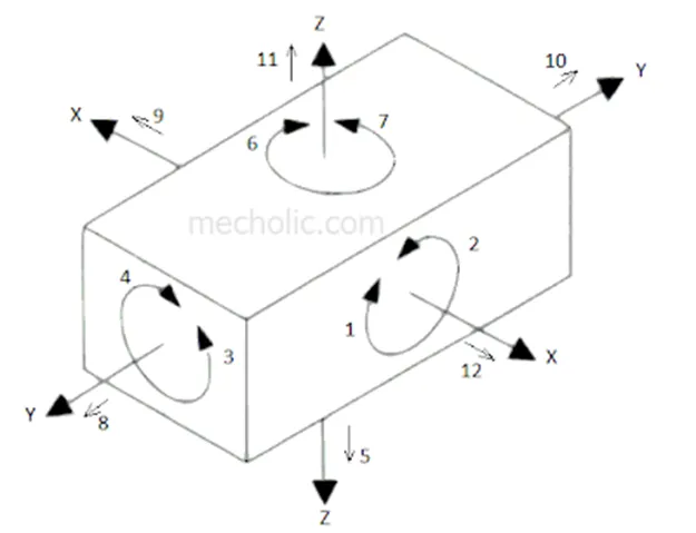
In this method, 9 Degrees of freedom is controlled.
Pins A, B, C on the base plane ( a plane parallel to the plane which contains X and Y axis) restrict the rotation of component about X axis and Y axis. It also limit the downward movement of component along z axis. Ie. 1,2,3,4 and 5 degrees of freedom is restricted.
Pins D, E is in plane parallel to the plane containing X and Z axes. It prevents the rotation of component about Z axis (6, 7 degree of freedom) and the movement of the body in along Y axis towards one direction (8 degree of freedom).
- Locators- In plastic design design locators is a part of attachment features to establish and maintain position of a part in a other part. In this project we are using two types of locators which is given below.
- 2 way and 4 way locators- In any kind of assembly before fixing the part to the mating part we need to fix the position of the part with respect to the mating part. In these cases we need to follow some engineering principles. In this project we are going to follow the 3-2-1 Principle. Any Part which has to be fixed during welding or machining process has to be fixed is having 12 degrees of freedom.
- Translation Movement along X Axis
- Translation Movement along Y Axis
- Translation Movement along Z Axis
- Rotational Movement along X Axis
- Rotational Movement along Y Axis
- Rotational Movement along Z Axis
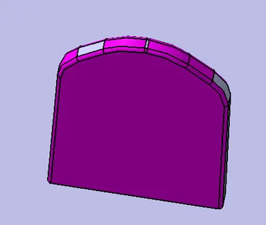
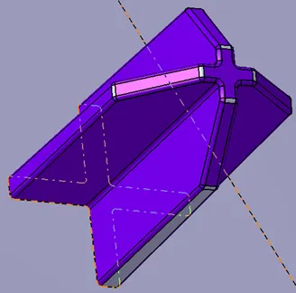
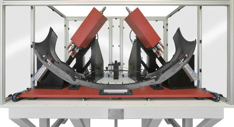
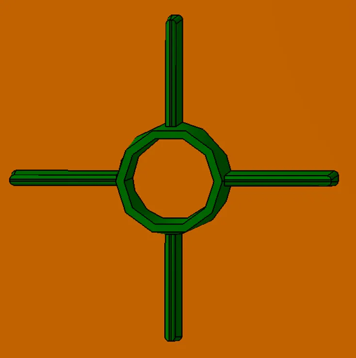
- Heat stakes- Heat Staking is a joining technology to join two or more parts together where at least one is made out of plastic. The process is used to melt and deform the plastic material using heat and force at a set process time. De-forming the plastic is achieved by heating it above the glass transition temperature and apply pressure. After heating, the materials are cooled down under pressure again to below the glass transition temperature.
- Procedure-
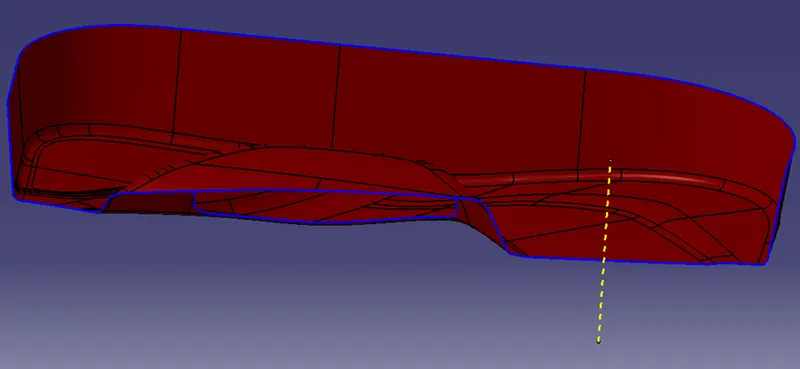
- Tooling axis- Tooling axis is nothing but the direction in which the core and cavity opens and closes. Design engineer works is to analyse the Class A surface and find out the best possible tooling direction keeping in mind all the draft angle is with respect to the tooling axis so that the component can be easily ejected from the moulds.
for creation of the tooling axis, we follow the normal to surface line method.
- First, ensure that the Class-A surface is properly joined and has no discontinuity. Select the boundary command from the toolbars and then select the Class-A surface. A boundary should only appear on the outer edges of the component.
- Then, we decide the proper tooling axis direction with respect to the given component (in this case it is the Z-axis direction).
- Generally, the tooling axis is created using bisecting lines method. But in this model, we observe that the side walls are not given any draft. Hence, we assume the axis normal to the base surface and parallel to side walls.
- We create a line normal to base surface by creating a point first on that surface and then create the line using the Normal to Surface method and taking the base surface and the point as references. This new line is considered as the tooling axis.
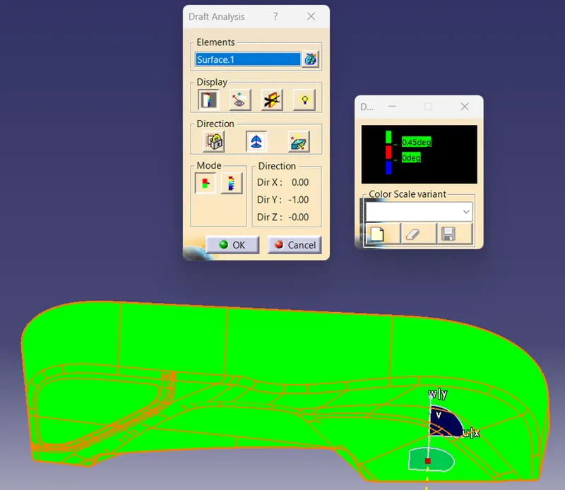
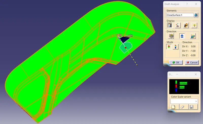
- Draft analysis- The draft analysis button within CATIA V5 will helps us quickly gather the draft angle on multiple surfaces without the need for tedious manual measurements. Here is a quick rundown of how the icon works when you have a given die direction.
to check whether our tooling axis is proper or not we do the draft analysis.
- Go to insert > analysis > feature draft analysis.
- Align the compass with the tooling axis.
- Then, click on the Class-A surface to see if the it is within the permissible limit of the draft values.
- The Class-A surface should turn green and then draft value should be given as 3 degrees.
- Draft analysis of class A surface-
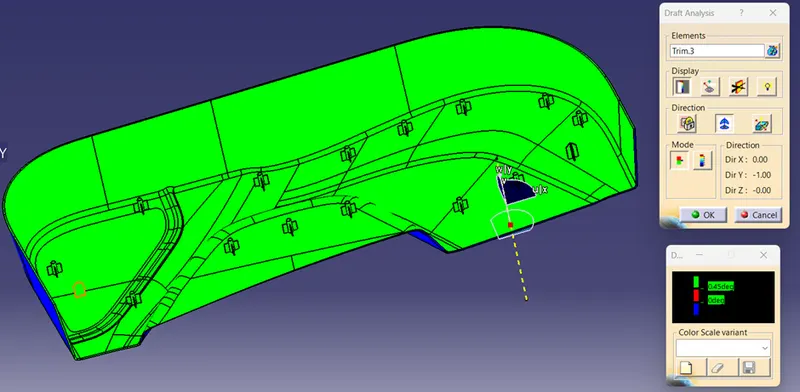
- Draft analysis of Door trim solid
- Draft analysis of door trim lower with engineering features
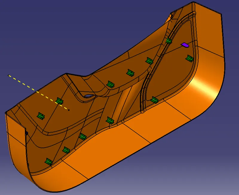
- Various views of complete design of Door trim lower with engineering features
- Isometric view-
- Front view-
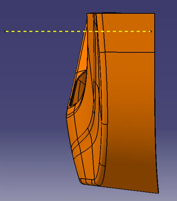
- Side view
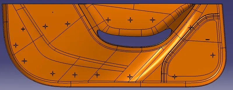
- Top view